
Operation Manual


35
A7 MIG Welder© Kemppi Oy 2018 1804
INTEGRATION GUIDE
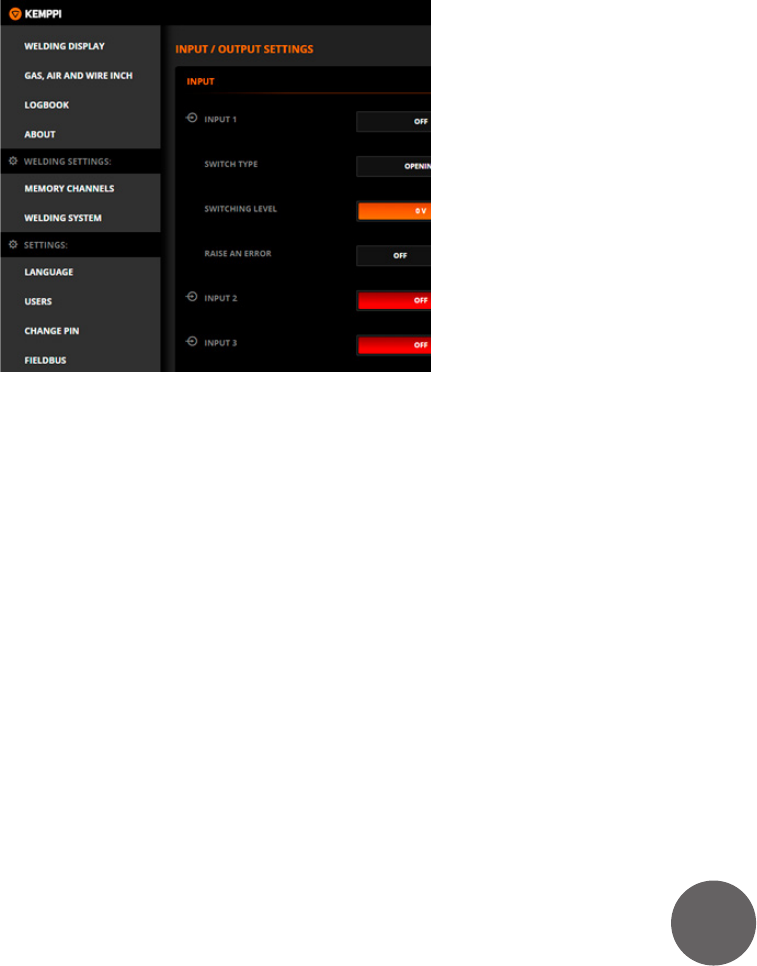
5.4 Inputs and outputs
If you have an I/O device connected to the system, it must
be congured by using the Web UI. Inputs and outputs
are o by default. Select the desired inputs and outputs
on and congure them according to their use. The inputs
are read and outputs written by using the digital robot
interface.
5.4.1 Inputs
Input 1–8
Set the inputs 1–8 ON or OFF. When an input is set on, other
options appear below. Congure the input by selecting
the switch type, switching level, and error options.
Switch type
Indicate the type of the switch used in your input. If you are
using an opening-action switch, select OPENING, and for
a closing-action switch select CLOSING. See Subsection
3.14.1, “Inputs” for more information.
Line level
Set the level of the input line. If you have connected the
input switch between pins 1 and 2, select 0 V. Otherwise,
if you have connected the switch between pins 2 and
3, select 24 V. See Subsection 3.14.1, “Inputs” for more
information.
Error triggering
An input can trig a warning or an error when activated.
If you want to enable error triggering, select WARNING
or ERROR according to your requirements. Set the error
triggering OFF for an ordinary input signal.
5.4.2 Outputs
Output 1–8
Set the outputs 1–8 ON or OFF by the means of hardware
installation. When an output is set on, other options
appear below. Congure the output by selecting polarity
for the output signal.
Polarity
Set the output polarity to LOW-ACTIVE if you want a logic
‘0’ to active the output, or HIGH-ACTIVE, if you want a logic
‘1’ to activate the output. When the output is active, it
actively pulls the signal down. In passive state the output
is pulled up by a resistor.