
Operation Manual


22
A7 MIG Welder© Kemppi Oy 2018 1804
INTEGRATION GUIDE
3.14.1 Installation
Switch the power source o and install the extension kit into the robot interface unit.
Ensure that all the cables are installed properly. Test the system by switching the power
source on and selecting the wire feeder between the WF1 and WF2 from the setup panel
or between the Wire feeder 1 and Wire feeder 2 from the web user interface. The extension
card should indicate the selection by amber LED lights. After successful installation, switch
the power source o and close the robot interface unit.
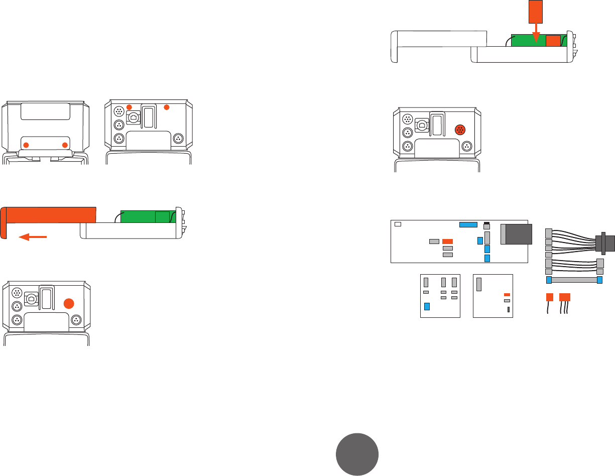
Follow these steps to install the extension kit:
7. Unscrew four screws, two from the front panel and two from the back panel.
8. Slide the top cover o by pulling from the handle in the front panel.
9. Remove the plug from the extension connector slot.
10. Mount the switching card side by side with the touch sensor card.
11. Fix the secondary wire feeder control connector to the extension connector slot
by using four screws.
12. Unplug the primary wire feeder from the motherboard A101 and from the touch
sensor card A102.
A101
X2
X2
X3
X3
A105
A102