
Operation Manual


20
A7 MIG Welder© Kemppi Oy 2018 1804
INTEGRATION GUIDE
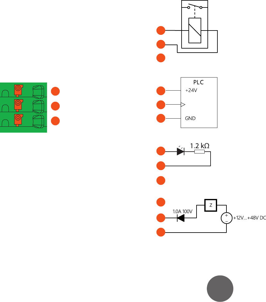
3.13.3 Outputs
The outputs have separate three-pole connectors, the rst
4 outputs on the main card and the last 4 outputs on the
extension card. The connectors have identical pinout (see
Figure 3.22, “Output connector pinout”). The outputs are
galvanically isolated from each other and from the other
hardware of the I/O device. The outputs have individual
short-circuit-protected +24 V DC power supplies, each
providing up to 100 mA of continuous current.
1
2
3
Figure 3.22: Output connector pinout
1. Supply out +24V, 100 mA
2. Output signal
3. Supply GND
The outputs are capable of driving loads up to 100 mA
and they are fully compatible with +24 V industrial logic.
The output signal is pulled up by a 10 k resistor. See the
following gures for connection examples. The output
conguration is described in Section 5.4, “Inputs and
outputs”.
1
2
3
Figure 3.23: Driving a relay or a valve
1
2
3
Figure 3.24: Interfacing with a PLC
1
2
3
Figure 3.25: Driving a LED indicator
1
2
3
Figure 3.26: Driving a load by using an external +12 V - +48 V
DC power supply