
Operation Manual


19
A7 MIG Welder© Kemppi Oy 2018 1804
INTEGRATION GUIDE
3.13.2 Inputs
The inputs have separate three-pole connectors, the
rst 4 inputs on the main card and the last 4 inputs on
the extension card. The connectors have identical pinout
(see Figure 3.20, “Input connector pinout”). The inputs are
galvanically isolated from each other and from the other
hardware of the I/O device. The inputs have individual
short-circuit-protected +24 V DC power supplies, each
providing up to 100 mA of continuous current.
1
2
3
Figure 3.20: Input connector pinout
1. Supply out +24V, 100 mA
2. Input signal
3. Supply GND
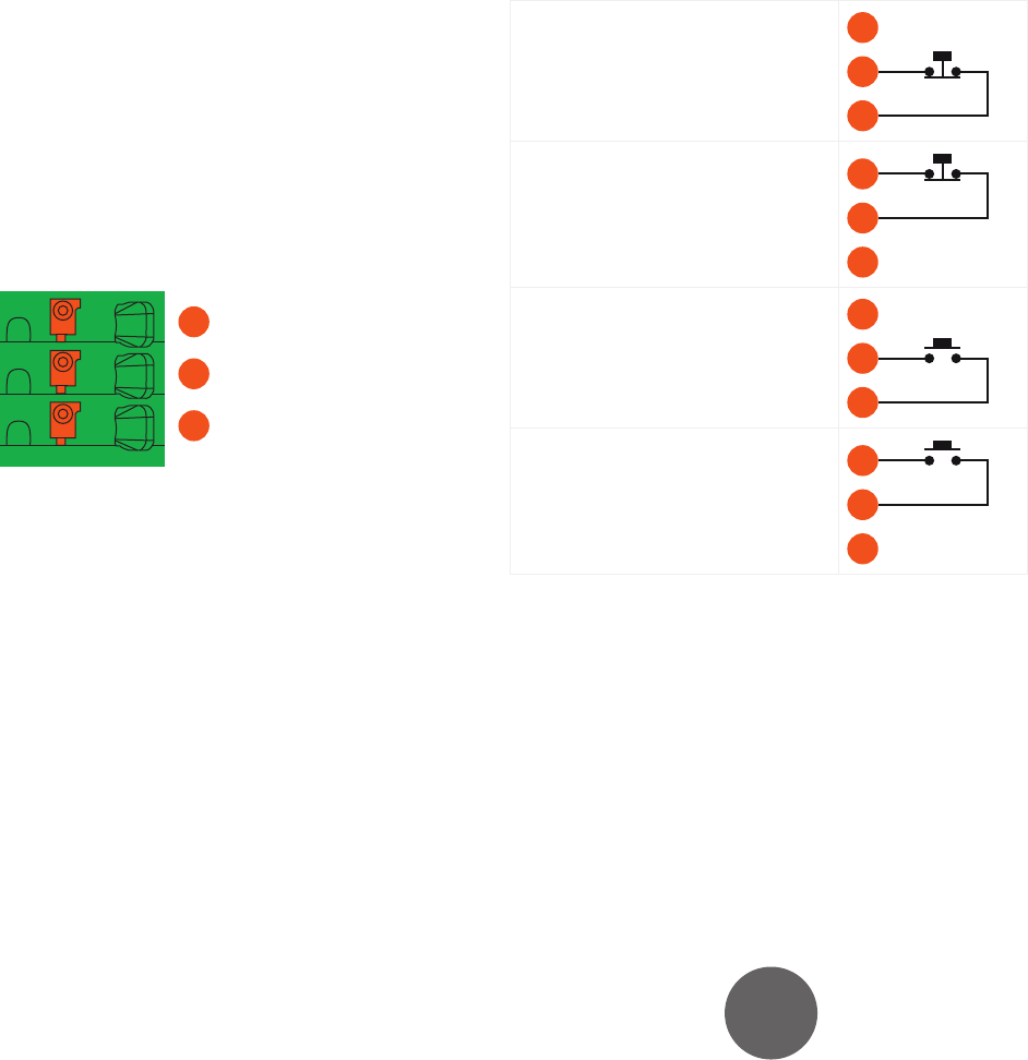
There are the four alternative ways of connecting the input
switches (see Figure 3.21, “Connecting input switches”).
Select one of these ways on the basis of your input circuitry
and the switch types used. The input conguration is
described in Section 5.4, “Inputs and outputs”.
Opening-action switch on 0 V line
(default)
1
2
3
Opening-action switch on +24 V line
1
2
3
Closing-action switch on 0 V line
1
2
3
Closing-action switch on +24 V line
1
2
3
Figure 3.21: Connecting input switches