
Operation Manual


14
A7 MIG Welder© Kemppi Oy 2018 1804
INTEGRATION GUIDE
3.10 Ethernet (web user interface server)
The welder system is equipped with a web user interface.
The server for the web user interface is in the robot
interface unit, and the connector for the server is at the
rear of the unit.
Connect the web user interface server to a laptop
computer, to another PC, or to a local area network by
using a CAT-5 or CAT-6 shielded Ethernet RJ-45 cable.
The communication speed of the network is 100 Mbps
(100Base-TX) and the maximum length of the cable is 90
m. Both crossover and direct cables are suitable.
The network conguration is described in Chapter 4,
“Accessing the web user interface”.
3.11 Emergency input functions
There are two emergency input functions in the system,
for the emergency stop and gate door switch.
• The emergency stop function halts the system
when the operator presses an emergency stop
button. After an emergency stop, the system
must be recovered manually.
• The gate door switch halts the system when a
protective gate door is opened. Shielding gas
testing, the torch clean-up function (compressed-
air valve), wire inch, wire retraction, and the touch
sensor can be used in this situation. The touch
sensor voltage is automatically lowered to a
safety level (max. 110 V). After a gate door switch
action, the system is recovered automatically.
Both inputs have a separate three-pin connector at the
rear of the robot interface unit. The connectors have
identical pinout (see Figure 3.14, “Emergency input
connector pinout”). The inputs are galvanically isolated
from each other and from the other hardware I/O of the
robot interface unit. The inputs have individual short-
circuit-protected +24 V DC power supplies, each providing
up to 100 mA of continuous current.
Figure 3.14: Emergency input connector pinout
A
B C
A. Supply out +24 V, 100 mA
B. Emergency input signal
C. Supply GND
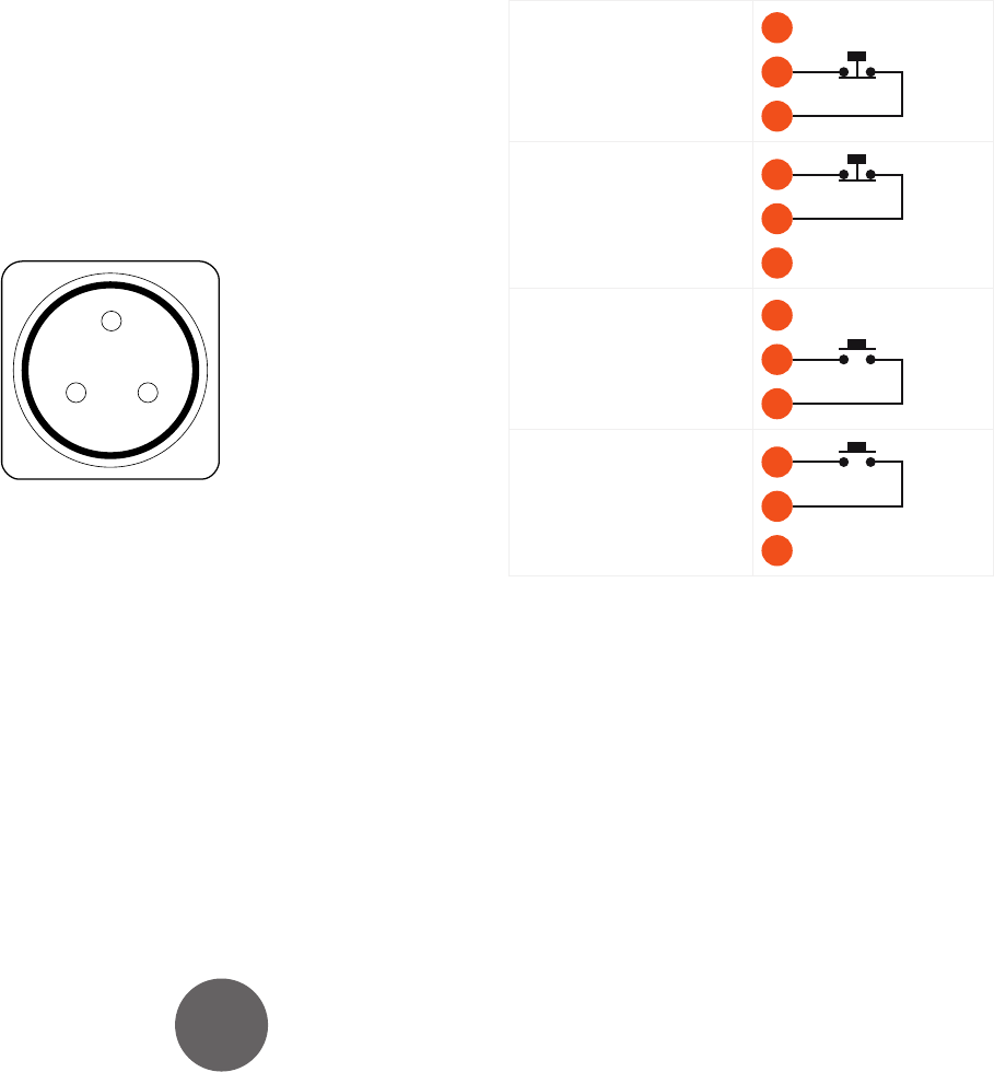
There are four alternative ways of connecting the
emergency stop and gate door switches (see Figure 3.15,
“Connecting the emergency stop switches”). Select one of
these ways on the basis of your emergency stop circuitry
and the switch types used. Connect the emergency stop
circuitry to the emergency input connector by using
custom cables.
The emergency inputs are congured via software. The
conguration is described in Subsection 5.1.7, “Emergency
stop settings.”
Opening-action switch on 0
V line (default)
A
B
C
Opening-action switch on
+24 V line
A
B
C
Closing-action switch on 0
V line
A
B
C
Closing-action switch on
+24 V line
A
B
C
Figure 3.15: Connecting the emergency stop switches