
Operation Manual


31
A7 MIG Welder© Kemppi Oy 2018 1804
INTEGRATION GUIDE
5.2 Digital robot interface
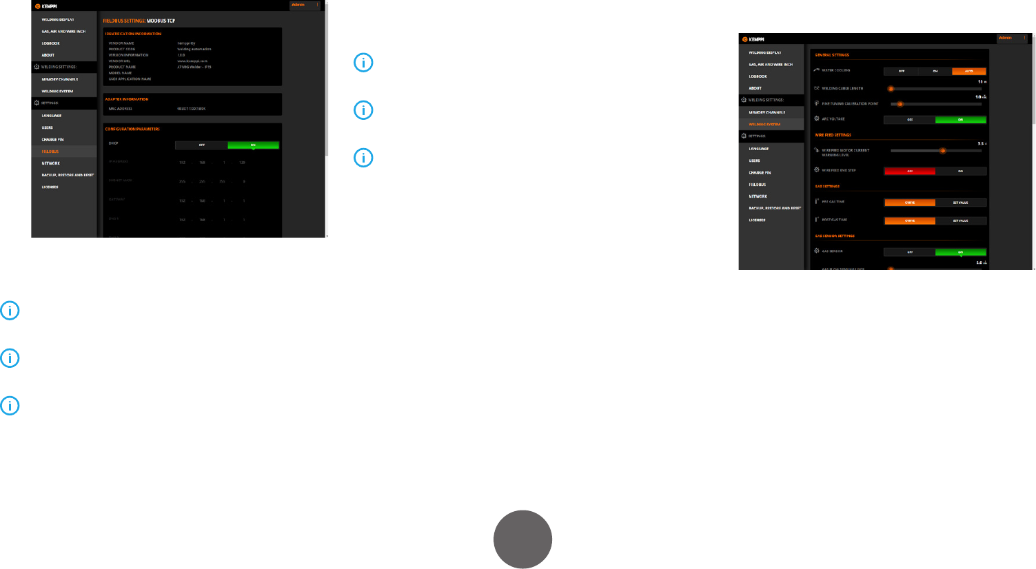
5.2.1 Fieldbus settings
To view the eldbus information and to congure the
settings, go to Settings > Fieldbus.
The contents of the eldbus conguration view depend
on the eldbus type. Congure the eldbus settings in
accordance with your eldbus network setup.
The eldbus settings are stored in the eldbus module.
If you replace the module, the settings must be recongured.
The eldbus settings are not included in the system
backup le.
A factory reset does not aect the eldbus settings.
5.2.2 Selecting the proper I/O table
Communication between the A7 MIG Welder system and a
welding robot is based on input/output tables (I/O tables)
exchanged between the machines by eldbus cyclic I/O
transmission. The tables contain binary-level functions
that the robot uses for controlling and monitoring the
welding system.
The I/O tables and functions are described in detail in
Chapter 6, “Digital robot interface I/O reference.”
The A7 MIG Welder default I/O table is number 15.
Avoid changing this setting in new installations.
All other tables except table 15 are compatible with
the corresponding tables in the KempArc Pulse system. Note
that the A7 MIG Welder does not support all KempArc Pulse
tables.
To specify a non-default I/O table, go to Welding settings >
Welding system > General robot settings and enter the I/O
table number in the Interface mode eld. Click on the Save
button, in the bottom bar, to save the changes.