
Instruction Manual


Circuitdescription: The module works with a phase control.
Description: This modul has a load capacity without additional
cooling of max. 3.5 ampere (at 110 V/AC approx. 385 VA, at 230 V/
AC approx. 805 VA). If the module with the cooling angle lies at
on a heat sink that is mounted insulated (ribbed cooler, minimum
dimension: approx. 10 x 6 x 2 cm) or any similar cooling metal sur-
face, loads up to 12 ampere (at 110 V/AC approx. 1320 VA, at 230
V/AC approx. 2720 VA) may be connected. Dimensions: approx. 60
x 56 x 20 mm without xing straps and without cooling angle.
Attention: Only glow lamps, motors with carbon slider (e.g. hand-
drilling machine), heating sets etc. are to be connected. Motors with
starting capacitor, uorescent and quartz lamps etc. cannot be cont-
rolled! Short circuits in the load circuit, overload and wrong connec-
tion lead to immediate destruction of the module. Since all modules
are tested carefully, no compensation on generosity is possible. Ple-
ase consider the VDE security regulations: e.g. pre-switched fuse,
contact protection on live parts, pull discharge for connection cables
etc.
Checklistfortroubleshooting: The module has to be screwed
on to a heat sink that is mounted insulated. If the fault current-
safety cutout releases, then there is an electric connection between
the connection to earth or phase connection of the current supply
and the cooling angle of the module or of the supply line to the
potentiometer or regulated consumer or a wrong connection of the
current supply. Please check the complete installation once again for
such inadmissible connections!
If you want to regulate drilling machines or the like, please make
sure that there is no electronic system already superposed to the
built-in motors (e.g. electronic gearshifting, soft start, etc.). It is not
possible to make 2 regulations at the same time (the built-in regu-
lation and this module).
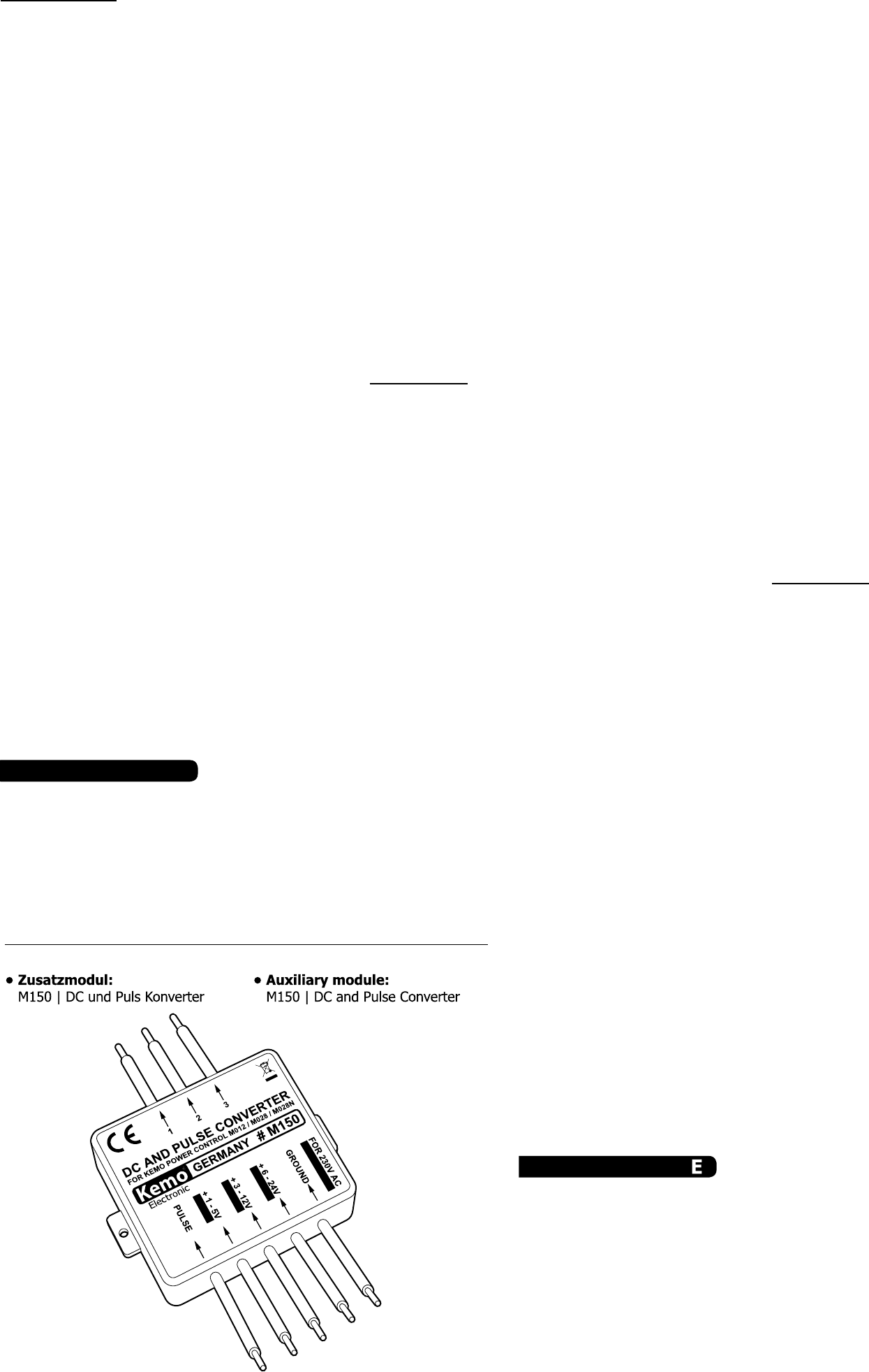
Available attachments: Auxiliary module M150. When super-
posing this module, it also possible to control the dimmer module
M028 with control voltages (1 - 5 V/DC or 3 - 12 V/DC or 6 - 24 V/
DC) or with TTL pulses (optionally in each case).
TechnicalData:
Operatingvoltage: 110 - 240 V/AC |Current: max. 12 A. At 110
V/AC this corresponds to max. 1320 VA and to max. 2880 VA at 240
V/AC. |Load: max. 2600 VA |Requiredpotentiometer: 470
k lin. (not enclosed) |Dimensions: approx. 60 x 56 x 20 mm
(without fastening straps)
SafetyinstructionsforKEMOModules.
Thesesafetyinstructionshavetobereadbeforeconnecting
themodule!
KEMO modules are manufactured according to DIN EN 60065 and
comply with the safety requirements with regard to manufacture.
All safety elements required for the nal assembly are listed in
the mounting instructions and must not be omitted for safety re-
gulations. The assembly and starting may only be carried out by
authorized persons who can also be held responsible for possible
damage.
The mounting instructions supplied by the manufacturer for com-
pletion of the appliances are to be observed. All safety facilities are
to be installed for permanent operation and must not be ignored
for personal safety. The same applies to the operating instructions
mentioned in the manufacturer‘s instructions.
The module must not be exposed to extreme temperatures (more
than 50°C) and humidity. The regulations for prevention of acci-
dents for electrical installations and operating material of the indus-
trial employer‘s liability insurance association are to be observed in
industrial facilities.
The module may become warm during operation depending on the
load. Therefore, it is advisable to t it into a well ventilated spot.
In schools, training centers and do-it-yourself workshops, the ope-
ration of these modules is to be supervised reliably by trained per-
sonnel.
Never place this module and the supply lines close to combustible or
inammable materials (e.g. curtains).
For all kits and modules which come into contact with a voltage
higher than 25 V, the VDE - safety instructions must be observed!
The installation resp. initial operation
may only be done by an expert! The
most important safety instructions are:
Protection against accidental contact for
all metallic parts which can carry more
than 25 V current. Strain reliefs at all
cables! In case of defect, components or
the module can burst! Therefore the mo-
dule resp. the printed circuit board have
to be installed in such a way that in this
case as well as in case of re no damage
occurs (installation into earthed metallic
cupboards or earthed metallic casings
and superposing of safety fuses).
Usodestinado:
Regulación de potencia en dispositivos
consumidores óhmicos hasta una tensi-
ón de servicio de 110 - 240 V/AC y un
consumo de corriente de menos de 13
amperios (el consumo de corriente má-
ximo del dispositivo consumidor debe
ser menos de 16 amperios). Dispositivos
consumidores óhmicos son: bombillas,
lámparas de halógeno, soldadores, cale-
facciones eléctricas, etc. Se pueden re-
gular los aparatos siguientes a dispositi-
Stromzuführung. Bitte überprüfen Sie noch einmal die gesam-
te Installation auf solche, nicht zulässigen Verbindungen!
Wenn Sie Bohrmaschinen oder ähnliches regeln wollen, dann
achten Sie bitte darauf, dass vor den eingebauten Motoren
nicht schon eine Elektronik vorgeschaltet ist (z.B. elektroni-
sche Gangschaltung, Sanftanlauf usw.). Es ist nicht möglich,
2 Regelungen gleichzeitig zu betreiben (die eingebaute Rege-
lung und dieses Modul).
LieferbaresZubehör: Zusatzmodul M150. Wenn dieses Mo-
dul vorgeschaltet wird, dann kann das Dimmermodul M028
auch mit Steuerspannungen angesteuert werden (1 - 5 V/
DC oder 3 - 12 V/DC oder 6 - 24 V/DC) oder auch mit TTL-
Impulsen (jeweils wahlweise).
TechnischeDaten:
Betriebsspannung: 110 - 240 V/AC |Strom:max. 12 A.
Das entspricht bei 110 V/AC max. 1320 VA und bei 240 V/AC
max. 2880 VA|Belastbarkeit: max. 2600 VA |Erforder-
lichesPotentiometer: 470 k lin. (liegt nicht bei) |Maße:
ca. 60 x 56 x 20 mm (ohne Befestigungslaschen)
SicherheitshinweisefürKEMO-Module.
DieseSicherheitshinweisemüssenvorAnschlussdes
Modulsgelesenwerden!
KEMO Module sind nach DIN EN 60065 gefertigt und halten
die Sicherheitsanforderungen fertigungsseitig ein. Alle für die
Fertigmontage benötigten Sicherheitselemente sind in der
Montageanweisung aufgeführt und dürfen aus sicherheits-
technischen Gründen nicht ausgelassen werden. Den Einbau
und die Inbetriebnahme dürfen nur autorisierte Personen vor-
nehmen, die auch die Haftung für eventuelle Schäden über-
nehmen.
Zu beachten sind die Montagehinweise, die der Hersteller zum
Komplettieren der Geräte mitliefert. Alle Sicherheitseinrichtun-
gen sind für den dauerhaften Betrieb einzurichten und dürfen
zur eigenen Sicherheit nicht unbeachtet gelassen werden, so-
wie die Bedienungshinweise in der Bedienungsanleitung.
Das Modul darf keinen zu hohen Temperaturen (über 50ºC)
und Feuchtigkeit ausgesetzt werden. In gewerblichen Einrich-
tungen sind die Unfallverhütungsvorschriften des Verbandes
der gewerblichen Berufsgenossenschaft für elektrische Anla-
gen und Betriebsmittel zu beachten.
Das Modul kann sich, je nach Belastung, während des Betrie-
bes erwärmen. Es sollte daher so eingebaut werden, dass es
gut belüftet wird.
In Schulen, Ausbildungseinrichtungen, Hobby- und Selbsthil-
fewerkstätten ist das Betreiben dieser Module durch geschul-
tes Personal verantwortlich zu überwachen.
Platzieren Sie dieses Modul und die Zuleitungen niemals in der
Nähe von brennbaren bzw. leicht entzündlichen Materialien
(z.B. Vorhänge).
Bei allen Bausätzen und Modulen, die mit einer höheren
Spannung als 25 V in Berührung kommen, müssen die VDE
Sicherheitsbestimmungen beachtet werden! Der Einbau bzw.
die Inbetriebnahme darf nur durch eine fachkundige Person
erfolgen! Zu den wichtigsten Sicherheitsbestimmungen gehö-
ren: Berührungsschutz für alle metallischen Teile, die über 25
V Spannung führen können. Zugentlastungen an allen Kabeln!
Im Falle eines Defekts können Bauteile oder das Modul plat-
zen! Das Modul bzw. die Platine muss so eingebaut werden,
dass in diesem Fall und auch im Brandfall kein Schaden ent-
stehen kann (Einbau in geerdete Metallschränke oder geerde-
te Metallgehäuse und Vorschalten von Sicherungen).
Intendeduse:
Output regulation in ohmic consumers with an operating vol-
tage of 110 - 240 V/AC and a current consumption of less
than 13 ampere (the peak current consumption of the consu-
mer must be less than 16 amperes). Ohmic consumers are:
electric light bulbs, halogen lamps, soldering irons, electric
heatings, etc. The following devices may be regulated at in-
ductive consumers: electric motors with carbon sliding con-
tacts.
P/Module/M028/Beschreibung/08026DI/KV040
2/4
vos consumidores inductivos: motores eléctricos con contactos
frotadores de carbón.
Descripcióndelcircuito: El módulo trabaja con control por
corte de onda.
Descripción: El módulo se puede cargar hasta 3,5 amperios
como máximo (con 110 V/AC aprox. 385 VA, con 230 V/AC
aprox. 805 VA) sin refrigeración adicional. Si el módulo con el
ángulo de refrigeración se ja planamente sobre un disipador
de color que se ha montado de manera aislada (radiador con
aletas longitudinales, medida mínima: aprox. 10 x 6 x 2 cm)
o una supercie metálica refrigerante semejante, se pueden
conectar cargas hasta 12 amperios como máximo (con 110 V/
AC aprox. 1320 VA, con 230 V/ AC aprox. 2720 VA). Medidas:
aprox. 60 x 56 x 20 mm sin eclisas de jación et sin ángulo de
refrigeración.
Atención: Solamente bombillas, motores con cursor de
carbón (p. ej. taladradoras portátiles), calefacciones etc. se
pueden conectar. ¡No es posible de regular motores con con-
densador de arranque, lámparas uorescentes y de cuarzo
etc.! Cortocircuitos en el circuito de carga, sobrecarga y una
conexión falsa resultan inmediatamente en la destrucción del
módulo. Puesto que cada módulo ha sido examinado con es-
mero antes del envío, una compensación no es posible. Por
favor, observe Vd. las normas de seguridad VDE: p. ej. fusibles
preconectados, protección contra contactos involuntarios a las
partes bajo tensión, descarga de tracción para los cables de
conexión etc.
Listadevericaciónparalalocalizacióndefallas:
Atornillar el módulo sobre un disipador de color que está mon-
tado de manera aislada. Cuando el interruptor de corriente
de falla dispara, hay una conexión eléctrica entre la cone-
xión a tierra o fase de la llegada de corriente y del ángu-
lo de refrigeración del módulo o de la línea de alimentación
hacia el potenciómetro o al dispositivo consumidor regula-
do o una falsa conexión de la llegada de corriente. Vericar
una vez más la installación completa por tales connexiones
no admisibles!
Si Vd. quiere regular taladradoras o semejante, atender a lo
que no hay ninguna electrónica ya preconectada a los motores
incorporados (p.ej. cambio de marchas electrónico, arrancada
suave, etc.). No es posible hacer 2 regulaciones al mismo tiem-
po (la regulación instalada y este módulo).
Accesorios disponibles: Módulo adicional M150. Al pre-
conectar este módulo, es también posible mandar este módulo
reductor de luz M028 con tensiones de control (1 - 5 V/DC o
3 - 12 V/DC o 6 - 24 V/DC) o bien con impulsos TTL (opcio-
nalmente).
Datostécnicos:
Tensióndeservicio: 110 - 240 V/AC |Corriente: máx. 12
A. Con 110 V/AC eso corresponde a 1320 VA como máximo y
a 2880 VA como máximo con 240 V/AC. |Carga: max. 2600
VA |Potenciómetro preciso: 470 k lin. (no va adjunto)|
Medidas: aprox. 60 x 56 x 20 mm (sin pestanas de jación)
InstruccionesdeseguridadparalosmódulosdeKEMO.
¡Leerlasinstruccionesdeseguridadantesdeconectar
elmódulo!
Los módulos de KEMO se fabrican según DIN EN 60065 y
cumplen con los requerimientos de seguridad con respecto a
la fabricación. Todos los elementos de seguridad precisos para
el montaje nal se especican en las instrucciones de montaje
y no se deben omitir por razones de seguridad. La incorpora-
ción y la puesta en servicio solamente deben efectuarse por
personas autorizadas que también salen garante de posibles
daños.
Se deben observar las instrucciones para el montaje que el
fabricador entrega para completar el aparato. Todas las in-
stalaciones de seguridad deben prepararse para la marcha
duradera y no deben desentenderse por seguridad propia así
como las instrucciones de servicio.
No exponer el módulo a altas temperaturas (más de 50°C)
ni a la humedad. En establecemientos industriales se deben
observar las instrucciones para prevenir los accidentes de la
asociación profesional industrial para las instalaciones eléctri-
cas y medios de producción.
El módulo puede calentarse durante la marcha dependiendo
de la carga. Por allí, tiene que instalarse de manera que sea
bien ventilado.
En escuelas, centros de formación profesional y en talleres
de hobby y de autoayuda, el servicio de los módulos se debe
vigilar de responsibilidad por personal enseñado.
Nunca poner este módulo y las líneas de alimentación cerca de
materiales fácilmente inamables (p.ej. cortinas).
¡Para todos los kits y módulos que pueden tener contacto con
una tensión de más de 25 V, las normas de seguridad VDE se
deben observar! ¡La instalación resp. la puesta en marcha so-
lamente se debe hacer por un perito! Las normas de seguridad
más importantes son: Protección contra contactos involunta-
rios para todas partes metálicas que pueden conducir más de
25 V de tensión. ¡Descargas de tracción a todos los cables!
¡En caso de defecto, elementos de construcción o el módulo
pueden reventar! Por eso el módulo resp. la placa de circuito
tienen que instalarse de manera que en este caso y también
en caso de incendio no puedan causar daños (instalación en
GB