
Installation Guide

44
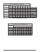
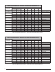
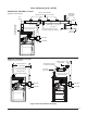
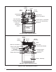
See Table 2 for
2” PVC pipe lengths
(field supplied)
3#3,3ERIES!&5%
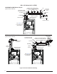
Figure 34. Horizontal & Vertical Venting
Normal snow level
VERTICAL VENTING w/ 2-Pipes
(Upflow Furnace Shown)
HORIZONTAL VENTING w/ 2-Pipes
(Upflow Furnace Shown)
Wall
Seal / caulk
around pipes
at wall
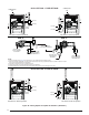
90° Elbow
12” Min.
Support system on
vertical rise
Support system on
vertical rise
First Support as Close
to Furnace as Possible
Flue Pipe must slope
upward 1/4” per foot
5’
7”
90° Elbows
90° Elbow
COMBUSTION AIR
Straps or other suitable supports
at minimum 5 ft. intervals (both pipes)
90° Elbows
Flue Pipe must slope
upward 1/4” per foot
First support as close
to furnace as possible
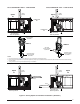
Rubber Grommet
Coupling with 2 hose
clamps (optional)
COMBUSTION AIR VENT PIPE
Rubber
Grommet
Straps or other suitable supports
at minimum 5 ft. intervals (both pipes)
COMBUSTION AIR
FLUE PIPE
Coupling with 2 hose
clamps (optional)
Rubber
Grommet
Coupling with 2 hose
clamps (optional)
FLUE PIPE
FLUE PIPE
See Table 2 for
2” PVC pipe lengths
(field supplied)