
Installation Guide

30
34!2450!$*534-%.43
0RE3TART#HECK,IST
Verify the polarity of the connections are correct, the
line voltage power leads are securely connected and
the furnace is properly grounded.
Verify the thermostat wires (R, W, Y, & G) are securely
connected to the correct leads on the terminal strip of
the circuit board.
Verify the gas line service pressure does not exceed 10.0
inches of W.C., and is not less than 4.5 inches W.C. for
natural gas. For LP gas the line service pressure must
not exceed 14 in. W.C., and must not be less than 11.0
in. W.C.
Verify the roll-out and manual reset switch is closed. If
necessary, press the red button to reset a switch. DO
./4INSTALLAJUMPERWIREACROSSASWITCHTODEFEAT
ITSFUNCTION If a switch reopens on startup, DO NOT
reset the switch without identifying and correcting the
fault condition.
Verify the blower door is in place, closing the door switch
in the line voltage circuit.
Verify the gas line has been purged and all connections
are leak free.
3TARTUP0ROCEDURES
Do not perform these steps until all of the checks in the
previous steps have been completed:
1. Set the thermostat to the lowest setting.
2. Turn off all electrical power to the furnace.
3. Follow the Operating Instructions on the label attached
to the furnace.
4. Set the thermostat above room temperature and verify
the Operating Sequence (page 31).
5. After 5 minutes of operation, set the thermostat below
room temperature and verify steps 9 - 10 of the Operating
Sequence.
6ERIFYING!DJUSTING)NPUT2ATE
The input rate must be verified for each installation to
prevent over-firing of the furnace. NOTE: The input rate
must not exceed the rate shown on the furnace rating plate.
At altitudes above 2,000 feet, it must not exceed that on
the rating plate less 4% for each 1,000 feet. To determine
the exact input rate, perform the following procedures:
1. Shut off all other gas fired appliances.
2. Start the furnace and run it for at least 3 minutes.
3. Measure the time (in seconds) required for the gas
meter to complete one revolution.
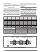
4. Convert the time per revolution to cubic feet of gas per
hour using Table 10 (page 40).
5. Multiply the gas flow rate in cubic ft per hr by the heating
value of the gas in Btu per cubic ft to obtain the input
rate in Btuh. See the example below.
%XAMPLE
s 4IMEFORREVOLUTIONOFAGASMETERWITHACUBIC
ft dial = 40 seconds.
s &ROMTable 10 read 90 cubic ft gas per hr.
s ,OCALHEATINGVALUEOFTHEGASOBTAINEDFROMGAS
supplier) = 1,040 Btu per cubic ft.
s )NPUTRATEX"TUH
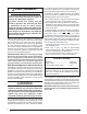
6. The manifold pressure must be set to the appropriate
value for each installation by a qualified installer, service
agency or the gas supplier.
WARNING:
$ONOTATTEMPTTODRILLTHEGASORIlCES5SEONLY
FACTORY SUPPLIED ORIlCES )MPROPERLY DRILLED
ORIlCES MAY CAUSE lRE EXPLOSION CARBON
MONOXIDEPOISONINGPERSONALINJURYORDEATH
a.) Obtain the manifold pressure setting required for
this installation by referring to Table 12 (page 41)
for Propane or Table 14 (page 42) or Table 15
(page 42) for Natural Gas.
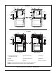
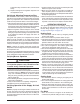
b.) Remove the regulator capscrew (Figure 30) from
the INLET side of the regulator.
c.) Slowly turn the adjustment screw inside the regulator
to obtain the appropriate manifold pressure.
NOTE: Turning the screw clockwise increases the
pressure and turning the screw counter-clockwise
decreases the pressure. To prevent backing the
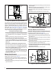
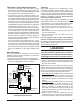
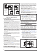
TWIN TERMINAL
FURNACE 1
6-Pin Wiring
Harness
TWINNING
CONTROL
BOARD
FURNACE
BOARD
FURNACE 2
TWIN TERMINAL
TWINNING
CONTROL
BOARD
FURNACE
BOARD
Expansion Port
6-Pin Wiring
Harness
Expansion Port
Expansion Port
Expansion Port
W
G
Y
C
R
THERMOSTAT
WG
YR
A/C
UNIT
W
G
Y
C
R
Figure 29. Single Stage Twinning
Capscrew
Figure 30. 2EGULATOR#APSCREW