
Installation Guide

17
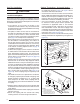
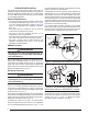
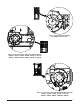
1. Shut off any electrical power to the furnace.
2. Label and disconnect the tubing and wires from the
pressure switch (1).
3. Remove two screws (2) securing the pressure switch
(1) to the side of the furnace.
4. Remove two 1/4” black plugs (3) on the opposite side
of the cabinet that the pressure switch will be relocated
to.
5. Position the pressure switch (1) in its new location and
secure it in place using the same screws (2) removed
in step 2
6. Insert the plugs (3) into the holes on the side that the
pressure switch (1) was removed from.
7. Reconnect the tubing and wiring to the pressure switch
(1) being careful that they will not fall into the burner
box.
CAUTION:
)TISEXTREMELYIMPORTANTTHATALLWIRESANDTUBES
BECORRECTLYREATTACHEDTOTHEPRESSURESWITCHS
&AILURETODOSO WILLRESULTINMALFUNCTIONOR
COMPROMISEDSAFETYFUNCTIONSOFTHEFURNACE
8. Check the furnace for proper operation as directed in
Startup and Adjustments section. If the furnace shuts
down during the pre-purge, the switch that measures
pressure in the header needs to be checked for correct
tubing connections.
Downflow Furnaces
WARNING:
4HEFURNACEMUSTNOTBEINSTALLEDDIRECTLYON
CARPETINGTILEORANYCOMBUSTIBLEMATERIALOTHER
THANWOODmOORING
WARNING:
&AILURETOINSTALLTHEDOWNmOWSUBBASEKITMAY
RESULTINlREPROPERTYDAMAGEORPERSONALINJURY
To install an *SL & *SM series gas furnace on combustible
flooring, a special sub-base is required. Downflow sub-
base kits are factory supplied accessories and are listed
according to the cabinet letter of the furnace. For ‘B’, ‘C’,
and ‘D’ size cabinets use Kit #904911. 0LEASEFOLLOWTHE
INSTRUCTIONSPROVIDEDWITHTHEKIT
A downflow sub-base kit is not necessary if the furnace
is installed on a factory or site-built cased air conditioning
coil. However, the plenum attached to the coil casing
must be installed so that its surfaces are at least 1” from
combustible construction.
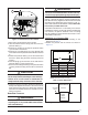
Installation on a Concrete Slab
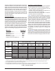
1.Create an opening in the floor according to the
dimensions in Table 3.
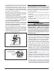
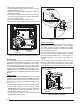
2. Position the plenum and the furnace as shown in
Figure 14.
3
1
Figure 13. 3#!0RESSURE3WITCH
2
Concrete
Floor
Furnace
Sheet
Metal
Plenum
Figure 14. &URNACEONA#ONCRETE3LAB
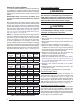
4ABLE#UTOUT$IMENSIONS
Model # $IMh!v $IMh"v
054D-24B 16
5/8
19
1/4
072D-24B 16
5/8
19
1/4
072D-35C 20
1/8
19
1/4
090D-35C 20
1/8
19
1/4
118D-45D 23
5/8
19
1/4
120D-45D 23
5/8
19
1/4
NOTE: Dimensions shown in Inches.
“A”
“B”
Opening in concrete floor