
Installation Guide

49
3$3-3ERIES!&5%
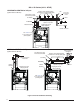
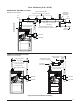
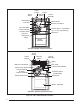
Figure 39. Horizontal & Vertical Venting
Support System on
Vertical Rise
First Support as Close
to Furnace as Possible
Couplings with 2
Hose Clamps (Optional)
FLUE PIPE
Coupling with 2 Hose
Clamps (Optional)
Straps or Other Suitable
Supports at minimum of 5 ft. Intervals
Upward Pitch - 1/4” per foot
(Flue Pipe)
First support placed as close
to furnace connection as possible
Wall
Normal
Snow Level
COMBUSTION AIR
90° Elbow
(both ends)
Seal/Caulk
Around Pipes
at Building
90°
Elbow
7”
12” Min.
90°
Elbow
90° Elbow
Support System on
Vertical Rise
COMBUSTION AIR
FLUE PIPE
FLUE PIPE
COMBUSTION AIR
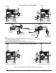
HORIZONTAL VENTING w/ 2-Pipes
(Upflow Furnace Shown)
VERTICAL VENTING w/ 2-Pipes
(Upflow Furnace Shown)
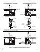
PVC Tee
PVC Trap
PVC Tee
PVC Trap
PVC Tee
PVC Trap
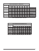
See Table 2 for 2” PVC pipe
lengths (field supplied)
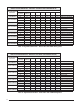
See
Table 2 for 2” PVC pipe
lengths (field supplied)
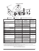
See Table 2 for 2” PVC pipe
lengths (field supplied)