
Installation Guide

22
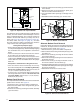
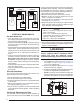
4. Carefully pull the blower assembly (4) out thru the front
of the furnace.
5. Remove all screws (5) securing bottom panel (6) to
bottom of furnace and front brace (7).
6. Lift up and slide bottom panel (6) out through front of
furnace.
7. Reinstall the blower assembly (4) in reverse order.
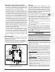
The drain lines can be routed out the left or right side of the
furnace, but must maintain a downward slope to ensure
proper condensate drainage. The J-trap may need to be
rotated to the side that matches your setup. For 92.1%
series, see
Figure 36 (page 46) & Figure 37 (page 47).
For 95.0% series, see Figure 41 (page 51). To rotate
the J-trap, loosen the clamp on the drain tube, rotate the
J-trap to either side, and retighten the clamp.
4HREEGENERALPRINCIPLESAPPLY
s %ACHCONDENSATEDRAINMUSTBETRAPPEDSEPARATELYUSING
a J-Trap or field supplied loop. After individually trapping
the condensate lines, it is acceptable to combine the
drains.
s 4HEREMUSTALWAYSBEADRAINATTACHEDTOTHECOLLECTOR
at the outlet of the secondary heat exchanger.
s 4HEREMUSTALWAYSBEADRAINATTHELOWESTPOINTOFTHE
venting system. NOTE: If using a condensate pump, the
furnace drain line must be installed above the pumps
water line.
%XCEPTIONSCLARIlCATIONSTOTHEGENERALRULES
s )FTHEVENTEXITSTHEFURNACEHORIZONTALLYTHEVENTMAY
be turned vertically with a tee. 4HEDRIPLEGFORMEDBY
THETEEMUSTINCLUDEADRAIN(Options 2,3,5,6,8,9,12
,13,16,17,19,20,21,23,24,31,32, & 34)
s )NCERTAINCASESITISPERMITTEDTODRAINTHEINDUCERBACK
into the top drain of the collector. 4HISDRAINMUSTNOT
SAGINTHEMIDDLE (Options 2,5,7,11,15,16,18,19,21,
23,25,27,29,30,32, & 33)
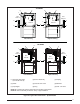
"OTTOM0ANEL2EMOVAL
The steps listed below describe how to remove the bottom
panel from the furnace. See Figure 23.
1. Remove the door (1) from the blower compartment.
2. Disconnect the blower motor wiring harness (2) from
the control board.
3. Remove two screws (3) securing the blower assembly
(4) to the furnace.
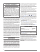
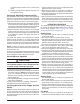
!LTERNATE"OTTOM0ANEL2EMOVAL
If the bottom panel cannot be removed using the previous
instructions, the steps below are an alternate method for
removing the bottom panel. See Figure 24.
1. Remove the door (1) from the blower compartment .
2. Remove all screws securing the bottom panel (2) to the
front brace (3).
3. Remove two screws (4) securing the furnace cabinet
to the blower deck (5).
4. Remove all screws (6) securing the furnace cabinet to
the bottom panel (2).
5. Remove the screw (7) securing the bottom corner of
the furnace cabinet to the front brace (3).
6. Carefully spread the bottom corner of the furnace cabinet
outwards while sliding the bottom panel (2) out through
the front of the furnace.
7. Reassemble the furnace in reverse order.
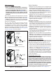
Figure 22. /PTIONAL06#0IPE)NSTALLATION
2” x 45
0
PVC
Elbow
2” PVC Pipe
2” x 3” PVC
Coupling
Coil Box
Figure 23. "OTTOM0ANEL2EMOVAL
6
7
5
1
2
3
4
1
4
2
7
3
6
5
Figure 24. !LTERNATE2EMOVAL-ETHOD