
Installation Guide

21
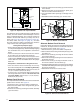
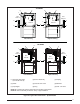
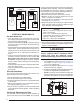
Typical Orientation
1. Install the PVC Tee vertically on the 2” vent pipe that is
extending out the side of the cabinet. Permanently bond
them together using appropriate primer and cement.
Refer to the typical orientation shown in
Figure 21.
2. Install the reducer or PVC trap (if supplied) on the bottom
end of the PVC Tee. Permanently bond them together
using appropriate primer and cement.
3. Install the 1/2” x 1/2” hose barb on the 2” PVC reducer.
NOTE: Do not over tighten! Use an adequate amount of
Teflon tape on the threads. Do not use liquid sealants.
4. Verify all connections and joints for tight fit and proper
alignment with other vent pipes.
Alternate Orientation
1. Install the 2” PVC Tee horizontally on the 2” vent pipe that
is extending out the side of the cabinet. Permanently bond
them together using appropriate primer and cement.
Refer to the alternate orientation shown in Figure 21.
2. Install the 2” PVC Elbow on the end of the 2” PVC Tee.
Permanently bond them together using appropriate
primer and cement.
3. Install the reducer or PVC trap (if supplied) on the bottom
end of the PVC Tee. Permanently bond them together
using appropriate primer and cement.
4. Install the 1/2” x 1/2” hose barb on the 2” PVC reducer.
NOTE: Do not over tighten! Use an adequate amount of
Teflon tape on the threads. Do not use liquid sealants.
5. Verify all connections and joints for tight fit and proper
alignment with other vent pipes.
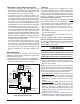
Optional PVC Pipe Installation
When running the 2” PVC pipe out through the top of the
*SD upflow furnace, there may be possible clearance
issues when transitioning the PVC pipe from 2” to 3”:
s )FTHESIZEOFTHE06#mUENEEDSTOBEINCREASEDFROM
2” to 3”, two, 2” x 45° PVC elbows may be used to
achieve the clearances needed between the coil box
and the 2” x 3” coupling. See Figure 22 (page 22).
s )NSTALLTHEvXvCOUPLINGINTHEVERTICALRUNONLY)FTHE
coupling is installed horizontally, it will allow water to build
up inside the furnace and cause a lock out condition.
s 4OAVOIDTHECLEARANCEISSUEITISRECOMMENDEDTHAT
the furnace be vented through the left side or the right
side of the cabinet.
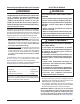
Condensate Drain Lines
)FTHEFURNACEISINSTALLEDINANAREAWHERETEMPERATURES
FALLBELOWFREEZINGSPECIALPRECAUTIONSMUSTBEMADE
FORINSULATINGCONDENSATEDRAINLINESTHATDRAINTOTHE
OUTDOORS)FCONDENSATEFREEZESINTHELINESTHISWILL
CAUSEIMPROPEROPERATIONORDAMAGETOTHEFURNACE)T
ISRECOMMENDEDTHATALLDRAINLINESONTHEOUTSIDEOF
THERESIDENCEBEWRAPPEDWITHANINDUSTRYAPPROVED
INSULATIONORMATERIALALLOWEDBYLOCALCODE
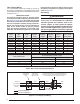
The placement of the condensate drain lines will depend
on the configuration selected in Table 4 (page 18).
PVC Components
IMPORTANT NOTES:
s "EFOREPERMANENTLYINSTALLINGTHESECOMPONENTS
ITISRECOMMENDEDYOUDRYlTTHEMlRSTTOENSURE
PROPERlTANDALIGNMENTWITHOTHERVENTPIPES
s 4HEv06#COMPONENTSSHOWNIN
Figure 21 are not
PROVIDEDINTHEEXTRAPARTSBAG(OWEVERTHE06#
4RAP0.CANBEPURCHASEDTHRUYOURLOCAL
DISTRIBUTOR
The 2” PVC tee, reducer, PVC Trap and 1/2” X 1/2” hose
barb are used when the inducer is rotated to vent out thru
the left or right side of the furnace cabinet. See Figure
21. NOTE: If supplied with your furnace, the NORDYNE
PVC trap (664659) may be used in place of the reducer
and 1/2” X 1/2” hose barb
The 1/2” X 3/4” hose barb can be used to route the
condensate drain to the outside of the cabinet. It must
be installed from inside the cabinet with the threaded
end inserted thru the 1 1/16” hole. The condensate drain
should be connected to the barbed end. Attach 1” PVC
drain line to the threaded end. See Figure 31 (page 33)
or Figure 32 (page 34) for hole location.
2” PVC TEE
2” x 1/2” PVC
Reducer
1/2” x 1/2”
Hose Barb
1/2” x 3/4”
Hose Barb
2” PVC Pipe from
Inline Drain Assembly
(Not Included)
1/2” Tubing Formed
into a Loop (Field Supplied)
1/2” Tubing
(Field Supplied)
2” PVC ELBOW
(Field Supplied)
PVC Trap
2” PVC Tee
2” x 1/2” PVC
Reducer
1/2” x 1/2”
Hose Barb
1/2” x 3/4”
Hose Barb
2” PVC Pipe from
Inline Drain Assembly
(Not Included)
1/2” Tubing Formed
into a Loop (Field Supplied)
1/2” Tubing
(Field Supplied)
PVC Trap
Installation of PVC Components (Typical Orientation)
Installation of PVC Components (Alternate Orientation)
Figure 21. 06##OMPONENTS