
Installation Guide

18
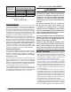
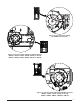
Inducer Assembly Rotation
WARNING:
)NDUCER ROTATION MUST BE COMPLETED BEFORE
THEFURNACEISCONNECTEDTOGASANDELECTRIC)F
BOTHUTILITIESHAVEBEENCONNECTEDFOLLOWTHE
SHUTDOWNPROCEDURESPRINTEDONTHEFURNACE
LABELANDDISCONNECTTHEELECTRICALSUPPLY
CAUTION:
)T IS GOOD PRACTICE TO LABEL ALL WIRES PRIOR
to disconnection. Wiring errors can cause
IMPROPERANDDANGEROUSOPERATION
1. Disconnect the electrical harness from the inducer
assembly.
2. Remove the inducer assembly ground wire from the
blower deck.
3. Remove 3 screws securing the inducer assembly to the
header box.
4. Rotate the inducer assembly to its new position.
5. Secure the inducer assembly to the header box by
reinstalling the three screws. If the inducer assembly
is rotated to the left or right side of the furnace, use the
extra screw provided in the parts package.
6. Remove the cabinet plug from side of furnace and
reinstall in hole on opposite side of cabinet.
7. Install in-line drain assembly and tubing.
8. Install all condensate drain lines. For 92.1% series,
refer to Figure 34, Figure 35, Figure 36, Figure 37, or
Figure 38. For 95.0% series, refer to Figure 39, Figure
40, Figure 41, or Figure 42.
9.Reconnect the electrical harness to the inducer
assembly.
10.Reconnect the inducer assembly ground wire to the
blower deck or door.
11.Verify operation as detailed on the furnace label.
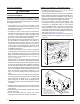
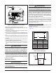
Pressure Switch Tubing
All upflow / horizontal furnaces have two switches, one
connected to the static tap on the inducer assembly and
the other to the collector box. Figure 15 (page 19) &
Figure 16 (page 19) display the proper routing of pressure
switch tubing for *SC & *SD furnaces. Downflow (*SL &
*SM) furnaces require only one switch connected to the
inducer’s static tap as shown in Figure 17 (page 19).
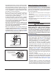
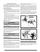
Alternate Pressure Switch Location
In some inducer orientations, the inducer pressure switch
may interfere with gas pipe installation. Determine the
side of the cabinet the gas pipe will enter and see if the
inducer pressure switch needs to be moved. If the pressure
switch interferes with the gas pipe, use these instructions
for relocating it to an alternate location:
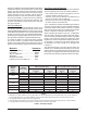
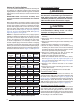
)NDUCER6ENTING/PTIONS
To increase installation flexibility, the inducer assembly can
be rotated up to 3 different positions. Each variation has
slightly different requirements with regard to condensate
disposal and, in some cases, the need to seal the furnace
cabinet.
)-0/24!.4 ./4% 4HE )NDUCER !SSEMBLY MUST
NEVERBEPOSITIONEDTOVENTDOWNWARDSONHORIZONTAL
installs.
Before using Table 4, the number of pipes (1-pipe or 2-pipe)
connected to the furnace must be known. Find the proper
furnace style (upflow, horizontal, or downflow) and then
the side that the pipes will exit from the furnace. Finally
select the option that properly matches your installation
type. For 92.1% series, Figure 34, Figure 35, Figure 36,
Figure 37, or Figure 38. For 95.0% series, see Figure 39,
Figure 40, Figure 41, or Figure 42.
NOTE: It is important that Direct Vent (2-pipe) systems
maintain an airtight flow path from the air inlet to the flue
gas outlet. The furnace ships from the factory with two
holes in the cabinet for the air inlet and flue gas outlet.
In certain configurations, it is necessary to remove and
relocate a plastic plug in the furnace cabinet. If changing
the position of the air inlet and flue gas outlet, it is required
that the previous hole be closed off with the plastic plug to
maintain air tightness in the furnace. The hole locations for
all furnace series are shown in Figure 31 and Figure 32.
#ONVENTIONAL0IPE
Vent
Direction
5PmOW
Horizontal
2IGHT
Horizontal
,EFT
Downflow
Right Option 21 N/A N/A Option 29
Up N/A Option 25 Option 26 Option 30
Left Option 22 N/A N/A Option 31
$IRECT6ENTPIPE
Vent
Direction
5PmOW
Horizontal
2IGHT
Horizontal
,EFT
Downflow
Right Option 23 N/A N/A Option 32
Up N/A Option 27 Option 28 Option 33
Left Option 24 N/A N/A Option 34
4ABLE6ENT)NDUCER"LOWER/PTIONS
#ONVENTIONAL0IPE
Vent
Direction
5PmOW
Horizontal
2IGHT
Horizontal
,EFT
Downflow
Up
Option 1 Option 7 Option 10 Option 15
Right Option 2 Option 8 N/A Option 16
Left Option 3 N/A Option 9 Option 17
$IRECT6ENTPIPE
Vent
Direction
5PmOW
Horizontal
2IGHT
Horizontal
,EFT
Downflow
Up
Option 4 Option 12 Option 14 Option 18
Right Option 5 Option 11 N/A Option 19
Left Option 6 N/A Option 13 Option 20