
Installation Guide

12
Vent Pipe Installation
CAUTION:
#OMBUSTION AIR MUST NOT BE DRAWN FROM A
CORROSIVEATMOSPHERE
This furnace has been certified for installation with zero
clearance between vent piping and combustible surfaces.
However, it is good practice to allow space for convenience
in installation and service.
s )N THE ABSENCE OF LOCAL CODES THE LOCATION OF ANY
combustion air inlet relative to any vent terminal must
be at least 8 inches. This includes installations involving
more than one furnace.
s 4HEQUALITYOFOUTDOORAIRMUSTALSOBECONSIDERED"E
sure that the combustion air intake is not located near
a source of solvent fumes or other chemicals which
can cause corrosion of the furnace combustion system.
(See page 5 for a sample list of substances).
s 2OUTEPIPINGASDIRECTASPOSSIBLEBETWEENTHEFURNACE
and the outdoors. Horizontal piping from inducer to
the flue pipe must be sloped 1/4” per foot to ensure
condensate flows towards the drain tee or PVC trap.
Longer vent runs require larger pipe diameters. Refer
to the Inducer & Venting Options section on page 18
for additional information.
s )FA$IRECT6ENTPIPESYSTEMISUSEDTHECOMBUSTION
air intake and the vent exhaust must be located in the
same atmospheric pressure zone. This means both
pipes must exit the building through the same portion of
exterior wall or roof as shown in Figure 34 (page 44)
or Figure 39 (page 49).
s 0IPINGMUSTBEMECHANICALLYSUPPORTEDSOTHATITSWEIGHT
does not bear on the furnace. Pipe supports must be
installed a minimum of every five feet along the vent run
to ensure no displacement after installation. Supports
may be at shorter intervals if necessary to ensure that
there are no sagging sections that can trap condensate.
It is recommended to install couplings along the vent
pipe, on either side of the exterior wall (Figure 34 or
Figure 39). These couplings may be required by local
code.
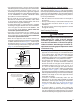
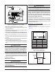
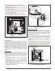
s )FBREAKABLECONNECTIONSAREREQUIREDINTHECOMBUSTION
air inlet pipe (if present) and exhaust vent piping, then
straight neoprene couplings for 2” or 3” piping with
hose clamps can be used. These couplings can be
ordered through your local furnace distributor. To install
a coupling:
1. Slide the rubber coupling over the end of the pipe that
is attached to the furnace and secure it with one of the
hose clamps.
2. Slide the other end of the rubber coupling onto the other
pipe from the vent.
3. Secure the coupling with the second hose clamp,
ensuring that the connection is tight and leak free.
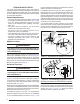
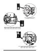
Outdoor Terminations - Horizontal Venting
s 6ENT AND COMBUSTION AIR INTAKE TERMINATIONS SHALL
be installed as shown in Figure 7 & Figure 8 and in
accordance with these instructions:
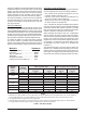
s 6ENTTERMINATIONCLEARANCESMUSTBECONSISTENTWITHTHE
NFGC, ANSI 2223.1/NFPA 54 and/or the CSA B149.1,
Natural Gas and Propane Installation Code. Table 16
(page 43) lists the necessary distances from the vent
termination to windows and building air intakes.
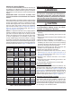
s 6ENT AND COMBUSTION AIR INTAKE TERMINATIONS MUST
be located to ensure proper furnace operation and
conformance to applicable codes. A vent terminal
must be located at least 3 feet above any forced air
inlet located within 10 feet. This does not apply to the
combustion air inlet of a direct vent (two pipe) appliance.
In Canada, CSA B149.1 takes precedence over these
instructions. See
Table 16 (page 43).
s !LLMINIMUMCLEARANCESMUSTBEMAINTAINEDTOPROTECT
building materials from degradation by flue gases. ee
(Figure 8).
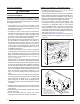
12” min. to maximum
expected snow level
(both pipes)
90° Elbow
Exhaust vent
option B
Exhaust vent
option A
Mounting kit faceplate
secured to wall with screws
(both pipes)
Combustion
air inlet
Exhaust vent
option C
18” Min.
36” Max.
8” Min.
36” Max.
(all positions)
Figure 7. )NLET%XHAUST0IPE#LEARANCES
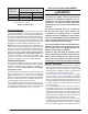
Note 2
Mechanical draft
vent terminal
Direct vent
terminal
50,000 Btuh
or less
Forced air inlet
Direct vent
terminal - more
than 50,000 Btuh
Mechanical
draft vent
terminal
Mechanical
draft vent
terminal
Less
than
10 ft.
3 ft.
NOTES:
1. All dimensions shown are
minimum requirements.
2. Exterior vent terminations must
be located at least 12” above the
maximum expected snow level.
Note 2
4 ft
4 ft
12 in.
12 in.
9 in.
Note 2
Figure 8. Vent Locations