
Installation Guide


9
CategoryIVenting
This furnace is listed as a Category I vented appliance.
Category I furnaces generally operate with a slight
negative pressure (draft) and must be vented vertically or
near vertical. Additionally it is important to guard against
excessive condensation.
wARNING:
Upon completion of the furnace installation,
carefullyinspect theentire ue systemboth
insideandoutsidethefurnacetoassureitis
properlysealed.Leaksintheuesystemcan
resultinseriouspersonalinjuryordeathdue
toexposureofueproducts,includingcarbon
monoxide.
wARNING:
Ventingintoanunlinedmasonrychimneyor
concretechimneyisprohibited.Thismayresult
in improper draft and excess condensation
forminginthechimney.
• Thisfurnacemustbevented incompliancewith
thecurrentrevisionoftheNationalFuelGasCode
(ANSI-Z223.1/NFPA54)andtheinstructionsprovided
below.Consultlocalcodesforspecialrequirements.
• InCanada,ventingshallconformtotherequirements
ofthecurrent(CAN/CGAB149.1or.2)installation
codes.Consultlocalcodesforspecialrequirements.
• CategoryIfurnaceinstallationsmustbeconnected
toafactorybuiltchimneyorventcomplyingwith
arecognizedstandard,oramasonryorconcrete
chimneylinedwithaliningmaterialacceptableto
theauthorityhavingjurisdiction.
• IntheU.S.,thisfurnacemustneverbeventedtoa
chimneyoruethatservicesareplaceorother
appliancedesignedtoburnsolidfuel.Ifthefurnace
vent is to be connected to a chimney serving a
replace,thereplacemustbesealedofffromthe
chimney.InCanada,commonventingwithareplace
ispermitted.ConsultB149.1andyourlocalcode
authority.
• Thisfurnacemaybeventedwithadedicatedventing
system or common vented with other Category I
appliances. The vent system dimensions and material
must conform to the NFGC or local Codes. Generally,
this means using Type B vent pipe or a lined masonry
chimney. When consulting the vent sizing tables in the
NFGC, the MAX capacity of the vent must be greater
than the furnaces high fire rate. The MIN capacity must
be lower than the low fire rate. If the venting system
is inappropriate for the furnace, the venting system
will need to be modified to comply with NFGC or local
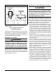
InstallationInAnUnconnedSpace
An unconfined space is an area including all rooms not
separated by doors with a volume greater than 50 cubic
feet per 1,000 Btuh of the combined input rates of all
appliances which draw combustion air from that space.
In general, a furnace installed in an unconfined space will
not require outside air for combustion. However, in homes
built for energy efficiency (low air change rates), it may
be necessary to provide outside air to ensure adequate
combustion and venting, even though the furnace is located
in an unconfined space. See example.
Example:
A space with a water heater rated at 45,000 Btuh
input and a furnace rated at 75,000 Btuh requires a
volume of 6,000 cubic feet [50 x (45 + 75) = 6,000] to
be considered unconfined. If the space has an 8 foot
ceiling, the floor area of the space must be 750 sq. ft.
(6,000 / 8 = 750).
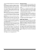
Alternate Method of Providing Air from Outside:
If acceptable under local Codes, it is permitted to provide
outside air using one opening (See NFGC). Generally,
confined spaces must have 2 openings in the space for
combustion air. One opening must be within 12 inches of
the ceiling, and the other must be within 12 inches of the
floor. However, an alternative method recently adopted by
the NFGC uses one opening within 12 inches of the top
of the space. This method may be used if it is acceptable
to the local codes.
Thefollowingconditionsmustbemet:
1. The opening must start within 12” of the top of the
structure and connect with the out of doors through
vertical or horizontal ducts or be ducted to a crawl or
attic space that connects with the out of doors.
2. The opening must have a minimum free area of 1 in
2
.
per 3,000 Btu per hour of the total input rating of all
equipment located in the enclosure.
3. The free area must not be less than the sum of all the
areas of the vent connectors in the enclosure.