
Installation Guide


7
ImportantInformation
• Provisionsmust be made during the installation
of this furnace that provide an adequate supply
ofair forcombustion.Furnace installation using
methodsotherthanthosedescribedinthefollowing
sectionsmustcomplywiththeNationalFuelGas
Code(NFGC)andallapplicablelocalcodes.
• Instructions for determining the adequacy of
combustionairforaninstallationcanbefoundinthe
currentrevisionoftheNFGC(ANSIZ223.1/NFPA54).
Consultlocalcodesforspecialrequirements.These
requirementsareforUSinstallationsasfoundin
the NFGC.
• TherequirementsinCanada(B149.1)arestructured
differently. Consult with B149.1 and local code
ofcialsforCanadianinstallations.
CAUTION:
Exhaust fans, clothes dryers, replaces and
otherappliancesthatforceairfromthehouse
totheoutdoorscancreateanegativepressure
insidethehouse,resultinginimproperfurnace
operationorunsafeconditionssuchasameroll
out.Itisimperativethatsufcientairexchange
with the outdoors is provided to prevent
depressurization.Additionalinformationabout
howtotestfornegativepressureproblemscan
befoundintheNFGC.
Air openings on top of the furnace and openings in closet
doors or walls must never be restricted. If the furnace is
operated without adequate air for combustion, the flame
roll-out switch will open, turning off the gas supply to the
burners. NOTE:Thissafetydeviceisamanuallyreset
switch. DO NOT install jumper wires across these
switchesto defeat their functionorreset a switch
withoutidentifyingandcorrectingthefaultcondition.
If a switch must be replaced, use only the correct sized part
specified in the Replacement Parts List provided online.
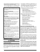
InstallationInAConnedSpace
A confined space is an area with volume less than 50
cubic feet per 1,000 Btuh of the combined input rates of
all appliances drawing combustion air from that space.
Furnace closets, small equipment rooms and garages are
confined spaces. Furnaces installed in a confined space
which supply heated air to areas outside the space must
draw return air from outside the space and must have the
return air ducts tightly sealed to the furnace.
The required sizing of these openings is determined by
whether inside or outside air is used to support combustion,
the method by which the air is brought to the space, and
by the total input rate of all appliances in the space. In
all cases, the minimum dimension of any combustion air
opening is 3 inches.
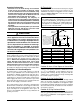
Air From Inside
If combustion air is taken from the heated space, the two
openings must each have a free area of at least 1 in
2
per
1,000 Btuh of total input of all appliances in the confined
space, but notlessthan100 in
2
of free area. See Figure
2 and the example below.
Example:
If the combined input rate of all appliances is less than
or equal to 100,000 Btuh, each opening must have a
free area of at least 100 in
2
. If the combined input rate
of all appliances is 120,000 Btuh, each opening must
have a free area of at least 120 in
2
.
Outdoor Air from a Crawl Space or Vented Attic
When the openings can freely exchange air with the
outdoors, each opening shall have a minimum free area
of 1 in
2
per 4,000 Btuh of total appliance input. The
openings shall exchange directly, or by ducts, with the
outdoor spaces (crawl or attic) that freely exchange with
the outdoors (Figure 3, page 8).
Outdoor Air Using Vertical Ducts
If combustion air is taken from outdoors through vertical
ducts, the openings and ducts must have a minimum
free area of 1in
2
per 4,000 Btuh of total appliance input.
In installations drawing combustion air from a ventilated
attic, both air ducts must extend above the attic insulation.
See Figure 4 (page 8).
Outdoor Air Using Horizontal Ducts
If combustion air is taken from outdoors through horizontal
ducts, the openings and ducts must have a minimum free
area of 1in
2
per 2,000 Btuh of total appliance input. See
Figure 5 (page 8).
Furnace
12" Max.
Water
Heater
Vent or
Chimney
NOTES:
Each opening must
be at least 100 sq. in.
or 1 sq. in. per 1,000
Btuh of total input rating,
whichever is greater.
Openings must start at
no more than 12 inches
from the top and bottom
of the enclosure.
12” Max.
See
Notes
See Notes
Figure2.CombustionAirDrawnfromInside
TotalInputRating
(Btuh)
MinimumFreeArea
(EachOpening)
RoundDuct
Diameter
40,000 100 in
2
12 inches
60,000 100 in
2
12 inches
80,000 100 in
2
12 inches
100,000 100 in
2
12 inches
120,000 120 in
2
13 inches
140,000 140 in
2
14 inches
160,000 160 in
2
15 inches