
Installation Guide


20
F(40°C).Forelectricalspecications,refertothe
furnacenameplateorTable2.
Grounding
wARNING:
Tominimizepersonalinjury,thefurnacecabinet
must have an uninterrupted or unbroken
electrical ground.The controls used in this
furnace require an earth ground to operate
properly.Acceptablemethodsincludeelectrical
wireorconduitapprovedforgroundservice.
Donotusegaspipingasanelectricalground!
IMpORTANT NOTES:
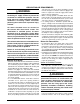
• Anelectricaldisconnectmustbeinstalledreadily
accessible from and located within sight of the
furnace.SeeFigure14orthewiringdiagramlabel
insideofthecontroldoor.Anyotherwiringmethods
mustbeacceptabletoauthorityhavingjurisdiction.
• Properlinevoltagepolaritymustbemaintainedin
orderforthecontrolsystemtooperatecorrectly.
Verifytheincomingneutrallineisconnectedtothe
whitewireandtheincoming“hot”lineisconnected
totheblackwire.Thefurnacewillnotoperateunless
thepolarityandgroundareproperlyconnectedas
showninFigure14.
• Ifreplacinganyoftheoriginalwiressuppliedwith
thefurnace,thereplacementwiremustbecopper
wiringandhaveatemperatureratingofatleast105°
Furnace
Model
*SA/*SK
Furnace
Input
(Btuh)
Cabinet
Width
(in.)
Nominal
Electrical
Supply
Maximum
Operating
Voltage
Minimum
Operating
Voltage
Maximum
Furnace
Amperes
Minimum
wire
Gauge
Maximum
FuseorCircuit
BreakerAmps*
045C-23A 45,000 14 1/4 115-60-1 127 103 6.3 14 15
054C-23A 54,000 14 1/4 115-60-1 127 103 6.3 14 15
072C-24B 72,000 17 1/2 115-60-1 127 103 9.7 14 20
072C-35C 72,000 21 115-60-1 127 103 9.0 14 15
090C-24B 90,000 17 1/2 115-60-1 127 103 9.7 14 20
090C-35C 90,000 21 115-60-1 127 103 9.0 14 15
108C-35C 108,000 21 115-60-1 127 103 15.2 12 30
126C-45D 126,000 24 1/2 115-60-1 127 103 15.2 12 30
ThermostatWireGauge
RecommendedThermostatWireLength
2-wire-Heating 4or5wire-Cooling
24 55 ft. 25 ft.
22 90 ft. 45 ft.
20 140 ft. 70 ft.
18 225 ft. 110 ft.
*
Time-delay fuses or circuit breakers are required.
Table2.WireLength&VoltageSpecications
Figure14.LineVoltageFieldWiring
Field Supplied
Disconnect w/in
Sight of Furnace
Field Supplied
Panel Connector
Field Supplied
Fused Service
Panel
Black (Hot)
White (Neutral)
Green or Bare
(Ground)
Black
White
Black
White
Black
White
Field Line Voltage Wiring
Factory Line Voltage Wiring
Ground
Ground
Junction Box (may be int. or ext.
to the furnace). These connections
can be made in the field supplied
disconnect at the furnace.
Ground