
Installation Guide

21
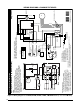
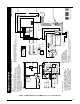
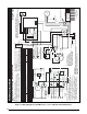
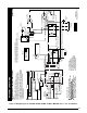
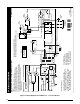
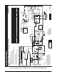
Figure 16. Wiring Diagram for CSH4BE, DT4BE, ET4BE, JT4BE, & MSH4BE Series - (4 & 5 Ton Models)
Outdoor
Fan Motor
R
C
CC
C
H
F
Dual
Capacitor
(Single Phase)
Field Supply
L1
Grd
L2
Grounding
Screw
C
S
T1 T2
L1 L2
HPS
Contactor
R
Start
Capacitor
Start Relay
5
2
htiw wolleY
hsaH kcalB
Comp
Low
Voltage
Terminals
See
Note 6
Defrost
Thermostat
TERMINAL OR GRAY WIRE
ODT(Select
Models Only)
T2
DFT
TEST
T1
T2
C
Y
O
W2
R
DFT
E
C
Y
O
W2
R
E
DF1 DF2
BlackBlack
Reversing Valve
Solenoid
S
CC
Defrost Control Board
1
CCH
Black
Red or Red Black
Yellow or Yellow Black
Black
Black or
Black White
Orange
Red
Red
Yellow
Black
Blue
Yellow
Black
Black
Black
Blue
Black
Yellow
esahP elgniS)noitceS roodtuO( pmuP taeH metsyS tilpS
WIRING DIAGRAM
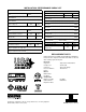
NOTES:
1. Disconnect all power before servicing.
2. For supply connections use copper conductors only.
3. Not suitable on systems that exceed 150 volts to ground
4. For replacement wires use conductors suitable for 105˚ C.
5. For ampacities and overcurrent protection, see unit rating plate.
6. Connect to 24 vac/40va/class 2 circuit. See furnace/air handler
installation instructions for control circuit and optional
relay/transformer kits.
Defrost Board Operation:
Closing during defrost.Rating: 1 Amp.Max.
Opens during defrost.Rating: 2HP at 230 Vac Max.
With DFT closed and “Y” closed, compressor run
time is accumulated. Opening of DFT during
defrost or interval period resets the interval to 0.
CC - Contactor Coil
CCH - Crankcase Heater
DFT - Defrost Thermostat
HPS - High Pressure Switch
RVS - Reversing Valve Solenoid
* - Hard Start Kit Field Installed
ODT - Outdoor Thermostat
1. Couper le courant avant de faire letretien.
2. Employez uniquement des conducteurs en cuivre.
3. Ne convient pas aux installations de plus de 150 volt a la terre.
710507-D
(Replaces 710507-C)
05/11
FIELD WIRING
LEGEND:
LOW VOLTAGE
HIGH VOLTAGE
Dual Capacitor
H
C
F
CCH
Compressor
Contacts
Compressor
Outdoor Fan Motor
R
C
S
L1
T1
L2
T2
E
Defrost Control Board
DFT
ODT (Select
Models Only)
Control
Logic
DF1
DF2
DFT
1
2
3
1
2
3
4
4
1
R
W2
O
Y
C
T2
T1
R
W2
O
Y
C
RVS
HPS
208/230V
CC
R
C
S