
Installation Guide

10
REFRIGERANT CHARGING
WARNING:
T4BE Split System Heat Pumps are shipped
charged with R410A refrigerant and ready
for installation. If repairs make it necessary
for evacuation and charging, it should only
be attempted by qualified trained personnel
thoroughly familiar with this equipment. Under
no circumstances should the owner attempt to
install and/or service this equipment. Failure to
comply with this warning could result in property
damage, personal injury, or death.
After refrigerant line connections are completed, it is
required that you leak check and evacuate the indoor
section and all line connections (using proper methods)
before finalizing the full system refrigerant charge.
• Toachieveratedcapacityandefciency,thecompressor
must be exposed to refrigerant for at least 24 hours
prior to running and then the compressor must be run
for a minimum of 12 hours.
• Coolingmodechargingchartsareapplicableonlyto
matched assemblies of NORDYNE equipment and listed
airflows for the indoor coil. T4BE outdoor units with
non-AHRI lsited indoor coils are not recommended and
deviations from rated airflows or non-listed combinations
may require modification to the expansion device and
refrigerant charging procedures for proper and efficient
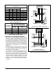
system operation. Refer to Figures 6 - 12 (pages 11 -
14) and Tables 4 - 9 (pages 16 & 17) for correct system
charging.
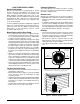
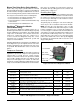
• Therefrigerantchargecanbecheckedandadjusted
through the service ports provided external to the
outdoor unit. Use only gage line sets which have a
“Schrader” depression device present to actuate the
valve. A common suction port for heating mode charging
is included and located on the compressor access panel
above the outdoor unit service valves.
• Heat Mode VericationTables (Tables 3 - 9, pages
16-18) are provided for quick reference when the unit
is in heating mode and for the inspection of the liquid
line pressures and temperatures.
• Ahigh-pressureswitchisfactory-installedandlocated
in the compressor discharge line internal to the
outdoor unit. The switch is designed to de-energize
the system when very high pressures occur during
abnormal conditions. Under normal conditions, the
switch is closed. If the discharge pressure rises above
575 psig, then the switch will open and de-energize
the outdoor unit. The switch will close again once the
liquid pressure decreases to 460 psig. Please note that
the switch interrupts the thermostat inputs to the unit.
Whentheswitchopensandthencloses,therewillbe
a 5 minute short cycling delay before the outdoor unit
will energize.
• A low-pressure switch is factory-installed in select
models only. If provided, this located in the suction line
internal to the outdoor unit. The switch is designed to
protect the compressor from a loss of charge. Under
normal conditions, the switch is closed. If the suction
pressure falls below 5 psig, then the switch will open
and de-energize the outdoor unit. The switch will close
again once the suction pressure increases above
20 psig. Please note that the switch interrupts the
thermostatinputstotheunit.Whentheswitchopens
and then closes, there will be a 5 minute short cycling
delay before the outdoor unit will energize.
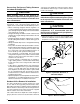
Charging the Unit in AC Mode with Outdoor
Temperatures Above 55° F
(for optimized sub-cooling of 10° F to 12° F)
1. Withthesystemoperatingatsteady-state,measurethe
liquid refrigerant pressure (in psig) at the outdoor unit
service valve.
2. Measure the liquid refrigerant temperature (in
Fahrenheit) at the service valve.
3. Determine the required liquid refrigerant pressure from
Figures 6 - 12 (pages 11 - 14).
• IfthepressuremeasuredinStep1isgreaterthan
the required liquid refrigerant pressure determined in
Step 3, then there is too much charge in the system.
Remove refrigerant and repeat Steps 1 through 3
until the system is correctly charged.
• IfthepressuremeasuredinStep1islessthanthe
required liquid refrigerant pressure determined in
Step 3, there is too little charge in the system. Add
refrigerant and repeat Steps 1 through 3 until the
system is correctly charged.