
Use and Care Guide

5
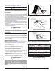
Figure 2. Loosening of Nut & Distributor Body
listed in Table 3, Table 4, or Table 5, (page 7). If the
oricemustbereplaced,followsteps1-5.
CAUTION:
To prevent damage to the unit or internal
components, it is recommended that two wrenches
be used when loosening or tightening nuts. Do not
over tighten!
1.Usingtwowrenches,loosenthenutanddistributorbody
as shown in Figure2.Turntheassemblynutcounter-clock-
wise until the orifice body halves are seperated.
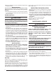
2.Insertalight-gaugewirehookbetweenthedistributorbody
and the restrictor orifice while being careful not to scratch
either part. Carefully remove the restrictor orifice from the
distributor body. See Figure3.
3.Checktheactualsizeoftheneworice.Thesizeisstamped
on its side. Do not use pin gauges to measure the orifice
diameter.
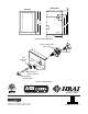
4. Insert the new orifice into the distributor body, rounded
end down. See Figure4.
CAUTION:
To prevent damage to the unit or internal
components, it is recommended that two wrenches
be used when loosening or tightening nuts. Do not
over tighten!
5.Realigntheassemblynutonthedistributorbodyandhand
tighten both components. Mark a line on both bodies and
thentightenanadditional1/4turnusingtwowrenches.The
movement of the two lines will show how much the nut is
tightened.Ifatorquewrenchisused,tightento10-12ft.
lbs.or14-16Nm.
Connecting the Linesets
NOTE: If installing a TXV, please follow the instructions
supplied with the kit. See Table2 for kit part numbers.
1.Removethegrommetfromthesuctionline,makingnote
of its orientation and fit.
2.Removethecoilaccessdoor.
3.Removetherubberplugfromthesuctionline.
4.InstalltheThermalExpansionValve(TXV). Please follow
the instructions supplied with the kit.
5.Route and cut both lineset tubes to proper length in
accordancewiththeoutdoorunitspecications.Verifythe
ends are round, clean, and free of any burrs.
6. Place the grommet on the suction line of the lineset.
NOTE:DONOTinstallthegrommetinthedoorcutoutat
this point. Allow sufficient distance to braze joint.
7. Connect the suction and liquid lineset tubes.
CAUTION:
It is recommended that a wet rag be wrapped around
the suction line in front of the close off plate before
applying heat. Failure to keep components cool
during brazing may result in structural damage,
premature equipment failure, or possible personal
injury.
Install restrictor with
rounded end down
in the distributor
Figure 4. Restrictor Insertion into Distributor Body
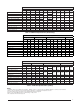
COIL HEIGHT CABINET
LIQUID LINE
TUBE KIT
18” A 921824
18” B 921825
24” B 921826
18” C 921827
24” C 921828
28” C 921829
24” D 921830
28” D 921831
Table 2. Liquid Line Tube kits
Figure 3. Removal of Orifice
Carefully remove the
restrictor orifice from
the distributor body