
Use and Care Guide

4
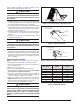
NOTE:The holesinthedrainpanextensionshouldbe
pressed over the nibs molded into the drain pan. Which
pair of holes to use will depend on whether the unit is
installed horizontalleftor horizontalright.Verify proper
positioning for clearance thru the top of the coil cabinet
beforeafxing.Thedrainpanextensioncanbeinstalled
and removed after the ductwork has been attached to the
cased coil.
7.ConnecttherefrigerantlinesasoutlinedintheRefrigerant
Lines Connection section.
8. Seal the enclosure as required to minimize air leakage.
9.Reinstallthecoilaccessdoor.
10.Restoreelectricalpowertothefurnace.
HorizontalRightInstallations
1. Disconnect all electrical power to the furnace.
2.Removethecoilaccessdoor.
3.Removetheplugandknockoutfromoneofthethreaded
holes in the horizontal drain pan.
CAUTION:
The knockout must be removed and discarded
to ensure proper condensate drainage. Failure to
do so may result in structural damage, premature
equipment failure, or possible personal injury.
4. Place the horizontal drain pan on the opposite side of the
coil. NOTE: If unit has 2 sets of knockouts, remove the
other set of knockouts in the coil spacing plates and insert
support rod.
5.Installplug(fromhorizontaldrainpan)intheopendrain
holeinthedrainpanatthebottomoftheunit.Thiswill
block bypass air from entering the system.
6. Slide the coil and the horizontal drain pan assembly back
into the unit.
7.Removethedrainlineknockoutfromthecoilaccessdoor.
Thiswillallowaccesstothehorizontaldrain.
8. Install drain pan extension (if supplied with unit).
NOTE:The holesinthedrainpanextensionshouldbe
pressed over the nibs molded into the drain pan. Which
pair of holes to use will depend on whether the unit is
installed horizontalleftor horizontalright.Verify proper
positioning for clearance thru the top of the coil cabinet
beforeafxing.Thedrainpanextensioncanbeinstalled
and removed after the ductwork has been attached to the
cased coil.
9.ConnecttherefrigerantlinesasoutlinedintheRefrigerant
Lines Connection section.
10. Seal the enclosure as required to minimize air leakage.
11.Reinstallthecoilaccessdoor.
12.Restoreelectricalpowertothefurnace.
Downflow Installations
C7 coils may be installed in downflow applications. It is
required that the furnace and coil cabinets are securely
mounted together before setting in place. Fossil fuel
applications require the coil to be placed in the supply air
stream only.
REFRIGERANT LINE CONNECTIONS
IMPORTANT NOTE TO INSTALLER
C7 Coils are not factory charged with refrigerant. It will
be necessary to evacuate the indoor coil and lineset
prior to charging. Refer to the outdoor unit installation
manual for detailed charging instructions.
System Depressurization
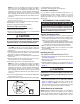
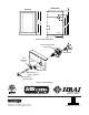
1.Removethecap(Figure1) from the end of the liquid line.
2.Verify pressurization by depressing the Schrader valve
on the end of the liquid line. Listen for any escaping gas.
If there is no pressure, test the coil for leakage.
• Ifleakageisfound,clearlymarkthelocationofthe
leak and return the coil to the distributor for processing.
• Ifnoleaksarefound,thecoilmaybeinstalled.
3. Depress the valve to relieve all pressure from the coil.
4.Removeanddiscardthevalvecoreandvalvecoreholder
on the liquid line.
5.Removetherubberplugfromthesuctionline.
Installing the TXV
(For Optional Bulkhead Mounted TXV’s)
1.InstalltheTXVretainingnutontotheinletendoftheTXV.
See Figure6(page8).
2.AddsmallamountofHVACapprovedthreadlocktothe
inletendoftheTXV.
3. Install the liquid line and accessory retaining nut onto the
endoftheTXV.Forliquidlinekitnumbers,seeTable2,
(page 5).
CAUTION:
To prevent damage to the unit or internal
components, it is recommended that two wrenches
be used when loosening or tightening nuts. Do not
over tighten!
4.AligntheretainingnutontheTXVbodyandhandtighten
both components. Mark a line on both bodies and then
tighten an additional ¼ turn using two wrenches. See
Figure 2 (page 5). NOTE: The movement of the two
lines will show how much the nut is tightened. If a torque
wrenchisused,tightento10-12ftlbsor14-16Nm.
Orifice Removal & Installation
NOTE: Before proceeding,performsteps1-3intheSystem
Depressurization section and confirm that the restrictor
orifice size meets the requirements outlined in the outdoor
unitinstallationmanual.Factorysuppliedoricesizesare
Suction
Line
Liquid
Line
Cap
Schrader
Valve
Figure 1. Suction & Liquid Line Locations