
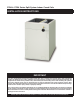
Use and Care Guide

3
• Close-offplatesareavailableinsomeairlterkits.Refer
totheReplacementPartsListforavailablepartnumbers.
Installthenecessaryclose-offplatesaroundtherefrigerant
linesanddrainlinewhererequired.Reinstallallinnerand
outer panels of the furnace/air handler that were previously
removed when installing the indoor coil.
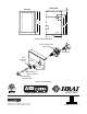
Upflow Installations
1. Disconnect all electrical power to the furnace.
2. Install the coil case on the furnace air discharge opening
and level it as needed to ensure proper condensate
drainage. If needed, make a plate to adapt the coil to the
air discharge opening. See Figure 5 (page 8) for coil
dimensions.
3. Make and install the plenum over the coil. Insulate as
required.
4. Seal the enclosure as required to minimize air leakage.
5.ConnecttherefrigerantlinesasoutlinedintheRefrigerant
Line Connection section.
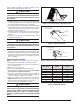
Horizontal Installations
C7 coils can be installed horizontally, but it is required that
the furnace and coil cabinets be securely mounted together
before setting in place. A horizontal drain pan kit must also
beinstalledunderthecoil. RefertoTable3, Table4, or
Table5 for available part numbers.
Horizontal Left Installations
1. Disconnect all electrical power to the furnace.
2.Removethecoilaccessdoor.
3.Removetheplugandknockoutfromoneofthethreaded
holes in the horizontal drain pan.
CAUTION:
The knockout must be removed and discarded
to ensure proper condensate drainage. Improper
drainage may result in structural damage, premature
equipment failure, or possible personal injury.
4. Install plug (from horizontal drain pan) in the open drain
holeinthedrainpanatthebottomoftheunit.Thiswill
block bypass air from entering the system.
5.Removethedrainlineknockoutfromthecoilaccessdoor.
Thiswillallowaccesstothehorizontaldrain.
6. Install drain pan extension (if supplied with unit).
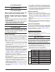
TXV KIT P/N SIZE OF A.C. OR H.P. (TONS)
R-22
REFRIGERANT
920662A 1.5or2
920663A 2.5
920664A 3
920665A 3.5
920666A 4
920667A 5
R-410A
REFRIGERANT
920668A 1.5or2
920669A 2.5
920670A 3
920671A 3.5
920672A 4
920673A 5
Table 1. TXV Kit Part Numbers
COIL INSTALLATION
WARNING:
ELECTRICAL SHOCK, FIRE OR
EXPLOSION HAZARD
Failure to follow safety warnings exactly could
result in serious injury or property damage.
Improper servicing could result in dangerous
operation, serious injury, death or property
damage.
• Beforeservicing,disconnectallelectricalpower
to the equipment.
• Whenservicingcontrols,labelallwirespriorto
disconnecting. Reconnect wires correctly.
• Verifyproperoperationafterservicing.
CAUTION:
The coil must be level to ensure proper condensate
drainage. An unlevel installation may result in
structural damage, premature equipment failure,
or possible personal injury.
General Information
C7 Series indoor cased coils are designed for upflow,
downflow, or horizontal applications and are equipped with
braze type refrigerant connections for easy installation. If a
TXVisnotinstalledbutrequiredforyourapplication,see
Table1 to determine the proper kit based on tonnage and
refrigerant type of the unit.
• Checkthecoilsoricesizeandconrmthatit’ssuitable
for application with the intended outdoor unit. Depending
onapplication,additionalinstallersuppliedoriceorTXV
may be required.
• Optionalcooling/heatingequipmentmustbeproperlysized
andinstalledinaccordancewiththefurnacemanufacturer’s
specifications and approved recommendations.
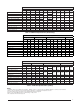
• Heatingonlyfurnaceaircirculatorsmayhavetobereplaced
withmulti-speedheating/coolingblowerstoupgradethe
airdelivery(CFM)whenanadd-oncoilisinstalled.Refer
to Table 3, Table 4, or Table 5, (page 7) for coil
specications, recommended CFM,and allowances for
pressure drop across the coil and filters.
• Verify that the air delivery of the furnace/air handler is
adequate to handle the static pressure drop of the coil,
filter, and duct work.
• Ifpreciseformingofrefrigerantlinesisrequired,acopper
tubing bender is recommended. Avoid sharp bends and
contact of the refrigerant lines with metal surfaces.
• Refrigerantlinesshouldbewrappedwithpressuresensitive
neoprene or other suitable material where they pass against
sharply edged sheet metal.
• Horizontalinstallationsrequireahorizontaldrainpankitto
be installed. See Table3, Table4, or Table5 for available
part numbers.