
Installation Guide


18
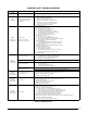
COMFORT ALERT TROUBLESHOOTING - CONTINUED
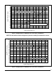
Table 10. LED Diagnostics - Continued
Status LED Status LED Description Status LED Troubleshooting Information
ALERT
Flash Code 6
(Yellow LED)
Open Start Circuit
Current only in run circuit
• Runcapacitorhasfailed
• Opencircuitincompressorstartwiringorconnections
— Check wiring and connectors between supply and the compressor S terminal
• Compressorstartwindingisdamaged
— Check compressor motor winding resistance
ALERT
Flash Code 7
(Yellow LED)
Open run circuit
Current only in start circuit
• Opencircuitincompressorrunwiringorconnections
— Check wiring and connectors between supply and the compressor R terminal
• Compressorrunwindingisdamaged
— Check compressor motor winding resistance
ALERT
Flash Code 8
(Yellow LED)
Welded Contactor
Compressor always runs
• Compressorcontactorhasfailedclosed
• Thermostatdemandsignalnotconnectedtomodule
ALERT
Flash Code 9
(Yellow LED)
Low Voltage
Control circuit < 17VAC
• Controlcircuittransformerisoverloaded
• Lowlinevoltage(contactutilityifvoltageatdisconnectislow)
• Checkwiringconnections
* Flash code number corresponds to a number of LED flashes, followed by a pause and then repeated. Trip and alert LED’s
flashing at same time means control circuit voltage is too low for operation.
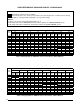
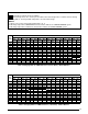
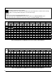
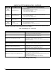
Table 11. Module Wiring Troubleshooting
Miswired Module Indication Recommended Troubleshooting Action
Green LED is not on, module does not power up
• DetermineifbothR & C module terminals are connected.
• Verifyvoltageispresentatmodule’sR & C terminals.
Green LED intermittent, module powers up only when compressor
runs
• DetermineifR & Y terminals are wired in reverse.
• VerifymodulesR&Cterminalshaveaconstantsource.
Trip LED is on, but system and compressor check OK
• VerifyY terminal is connected to 24VAC at contactor coil.
• Verifyvoltageatcontactorcoilfallsbelow0.5VACwhenoff.
• Verify24VACispresentacrossY & C when thermostat demand signal is preset. If not,
R & C are reversed wired.
TRIP LED & ALERT LED flashing together • VerifyR & C terminals are supplied with 19 - 28VAC.
ALERT Flash CODE 3 displayed incorrectly
(Compressor short cycling)
• VerifyY terminal is connected to 24VAC at contactor coil.
• Verifyvoltageatcontactorcoilfallsbelow0.5VACwhenoff.
ALERT Flash Code 5, 6, or 7 displayed incorrectly
(Open Circuit, Open Start Circuit or Open Run Circuit)
• Verify the compressorrun andstartwires are routedthrough the module’scurrent
sensing holes.
• VerifytheY terminal is connected to 24VAC at contactor coil.
• Verifyvoltageatcontactorcoilfallsbelow0.5VACwhenoff.
ALERT Flash Code 6 (Open Start Circuit) displayed for Code 7
(Open Run Circuit) or vice-versa
• Verifythecompressorrunandstartwiresareroutedthroughthecorrectmodulesensing
holes.
ALERT Flash Code 8 displayed incorrectly (Welded Contactor)
• Determineifmodule’sY terminal is connected.
• VerifyY terminal is connected to 24VAC at contactor coil.
• Verify24VACispresentacrossY & C when thermostat demand signal is present. If
not, R & C are reversed wired.
• Verifyvoltageatcontactorcoilfallsbelow0.5VACwhenoff.
• ReviewThermostatDemandWiring(page10)forY & C wiring.