
Operating Guide

5
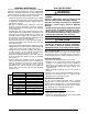
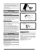
Figure 2. Loosening of Nut & Distributor Body
Install restrictor with
rounded end down
in the distributor
Figure 4. Restrictor Insertion into Distributor Body
2. Insert a light-gauge wire hook between the distributor
body and the restrictor orifice while being careful not
to scratch either part. Carefully remove the restrictor
oricefromthedistributorbody.SeeFigure3.
3.Checktheactualsizeoftheneworice.Thesizeis
stamped on its side. Do not use pin gauges to measure
the orifice diameter.
4. Insert the new orifice into the distributor body, rounded
enddown.SeeFigure4.
CAUTION:
To prevent damage to the unit or internal
components, it is recommended that two
wrenches be used when loosening or tightening
nuts. Do not over tighten!
5.Realigntheassemblynutonthedistributorbodyand
hand tighten both components. Mark a line on both
bodiesandthentightenanadditional1/4turnusingtwo
wrenches.Themovementofthetwolineswillshowhow
much the nut is tightened. If a torque wrench is used,
tightento10-12ft.lbs.or14-16Nm.
Connecting the Linesets
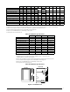
NOTE:IfinstallingaTXV,pleasefollowtheinstructions
suppliedwiththekit.SeeTable1(pg3)forkitpartnumbers.
1.Remove the grommet from the suction line, making
note of its orientation and fit.
2.Removethecoilaccessdoor.
3.Removetherubberplugfromthesuctionline.
4.Install the Thermal Expansion Valve (TXV). Please
follow the instructions supplied with the kit.
5.Routeandcutbothlinesettubestoproperlengthin
accordancewiththeoutdoorunitspecications.Verify
the ends are round, clean, and free of any burrs.
6. Place the grommet on the suction line of the lineset.
NOTE:DONOTinstallgrommetinthedoorcutoutat
this point. Allow sufficient distance to braze joint.
7. Connect the suction and liquid lineset tubes.
CAUTION:
It is recommended that a wet rag be wrapped
around the suction line in front of the close
off plate before applying heat. Failure to keep
components cool during brazing may result
in structural damage, premature equipment
failure, or possible personal injury.
8.Braze the individual connections with dry nitrogen
flowing through the joints.
IMPORTANT: To prevent internal oxidation and scaling
from occuring, braze all connections with dry nitrogen
flowing through the joints.
9.Installthegrommetinthedoorcutout.Verifythegrommet
is evenly aligned around the tube and securely positioned
in the door cutout.
Figure 3. Removal of Orifice
Carefully remove the
restrictor orifice from
the distributor body
Completing the Installation
1.Checkthesystemforleaks,includingthelinesetand
the brazed joints.
2.Evacuatethesystemofmoistureandnon-condensables
to prevent low efficiency operation or damage to the
unit.Thesuggestedrangeofevacuationis350-500
microns.
3. Charge the system with refrigerant. Please Refer to
the outdoor unit installation manual for additional
charging instructions.
4. Install the coil access door (if removed).
5.Properlydisposeofallremovedparts.
6. Apply power to the unit.