
Operating Guide

4
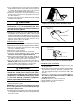
CAUTION:
The knockout must be removed and discarded
to ensure proper condensate drainage. Improper
drainage may result in structural damage,
premature equipment failure, or possible
personal injury.
4. Install plug (from horizontal drain pan) in the open drain
holeinthedrainpanatthebottomoftheunit.Thiswill
block bypass air from entering the system.
5.Removethedrainlineknockoutfromthecoilaccess
door.Thiswillallowaccesstothehorizontaldrain.
6. Install drain pan extension (if supplied with unit).
NOTE:Theholesinthedrainpanextensionshouldbe
pressed over the nibs molded into the drain pan. Which
pair of holes to use will depend on whether the unit is
installedhorizontalleftorhorizontalright.Verifyproper
positioning for clearance thru the top of the coil cabinet
beforeafxing.Thedrainpanextensioncanbeinstalled
and removed after the ductwork has been attached to
the cased coil.
7. Connect the refrigerant lines as outlined in the
RefrigerantLinesConnectionsection.
8. Seal the enclosure as required to minimize air leakage.
9.Reinstallthecoilaccessdoor.
10.Restoreelectricalpowertothefurnace.
HorizontalRightInstallations
1.Disconnectallelectricalpowertothefurnace.
2.Removethecoilaccessdoor.
3.Removetheplugandknockoutfromoneofthethreaded
holes in the horizontal drain pan.
CAUTION:
The knockout must be removed and discarded
to ensure proper condensate drainage. Failure
to do so may result in structural damage,
premature equipment failure, or possible
personal injury.
4. Place the horizontal drain pan on the opposite side of
the coil. NOTE: If unit has 2 sets of knockouts, remove
the other set of knockouts in the coil spacing plates and
insert support rod.
5.Installplug(fromhorizontaldrainpan)intheopendrain
holeinthedrainpanatthebottomoftheunit.Thiswill
block bypass air from entering the system.
6. Slide the coil and the horizontal drain pan assembly
back into the unit.
7.Removethedrainlineknockoutfromthecoilaccess
door.Thiswillallowaccesstothehorizontaldrain.
8. Install drain pan extension (if supplied with unit).
NOTE:Theholesinthedrainpanextensionshouldbe
pressed over the nibs molded into the drain pan. Which
pair of holes to use will depend on whether the unit is
installedhorizontalleftorhorizontalright.Verifyproper
positioning for clearance thru the top of the coil cabinet
beforeafxing.Thedrainpanextensioncanbeinstalled
and removed after the ductwork has been attached to
the cased coil.
9. Connect the refrigerant lines as outlined in the
RefrigerantLinesConnectionsection.
10.Sealtheenclosureasrequiredtominimizeairleakage.
11.Reinstallthecoilaccessdoor.
12.Restoreelectricalpowertothefurnace.
Downflow Installations
C7 coils may be installed in downflow applications. It is
required that the furnace and coil cabinets are securely
mounted together before setting in place. Fossil fuel
applications require the coil to be placed in the supply
air stream only.
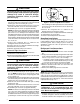
Refrigerant Line Connections
System Depressurization
1.Removethecap(Figure1)fromtheendoftheliquid
line.
2.VerifypressurizationbydepressingtheSchradervalve
on the end of the liquid line. Listen for any escaping gas.
If there is no pressure, test the coil for leakage.
• Ifleakageisfound,clearlymarkthelocationofthe
leak and return the coil to the distributor for processing.
• Ifnoleaksarefound,thecoilmaybeinstalled.
3. Depress the valve to relieve all pressure from the coil.
4.Remove and discard the valve core and valve core
holder on the liquid line.
5.Removetherubberplugfromthesuctionline.
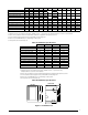
OriceRemoval&Installation
NOTE:Beforeproceeding,performsteps1-3intheSystem
Depressurization section and confirm that the restrictor
orifice size meets the requirements outlined in the outdoor
unitinstallationmanual.Factorysuppliedoricesizesare
listedinTables2Aor2B(page7).Iftheoricemustbe
replaced,followsteps1-5.
CAUTION:
To prevent damage to the unit or internal
components, it is recommended that two
wrenches be used when loosening or tightening
nuts. Do not over tighten!
1.Usingtwowrenches,loosenthenutanddistributorbody
asshowninFigure2.Turntheassemblynutcounter-
clock-wise until the orifice body halves are seperated.
Suction
Line
Liquid
Line
Cap
Schrader
Valve
Figure 1. Suction & Liquid Line Locations