
User's Manual


Table Of Contents
- KH1264 ISSUE 1
- CHAPTER 1
- CHAPTER 2
- CHAPTER 3
- CONTENTS
- ILLUSTRATIONS
- Figure 1 - Transceiver (DTX-A3): Module Locations 34
- Figure 2 - Drive Control Unit (GTX-A24): Module Locations 35
- Figure 3 X-band Upmast Transceiver (DTX-A3): Functional Diagram Figure 3 38
- Figure 4 X-band Upmast Transceiver (DTX-A3): Interconnection Diagram Figure 4 39
- Figure 5 - Drive Control Unit (GTX-A24): Block Diagram 319
- CHAPTER 4
- CONTENTS
- TABLES
- ILLUSTRATIONS
- Figure 1 - Transceiver (DTX-A3): Installation Dimensions 49
- Figure 2 - Transceiver (DTX-A3): Mast Mounting 410
- Figure 3 - Transceiver (DTX-A3): Fitting Kit 411
- Figure 4 - Suggested Antenna Lifting Arrangement 412
- Figure 5 - Drive Control Unit (GTX-A24): Installation Dimensions 413
- Figure 6 - Mains Isolator: Installation Dimensions 414
- Figure 7 - Transceiver (DTX-A3): Cableform Routing 419
- Figure 8 - Drive Control Unit (GTX-A24): Cableform Routing 420
- Figure 9 - Cable Gland: Assembly 421
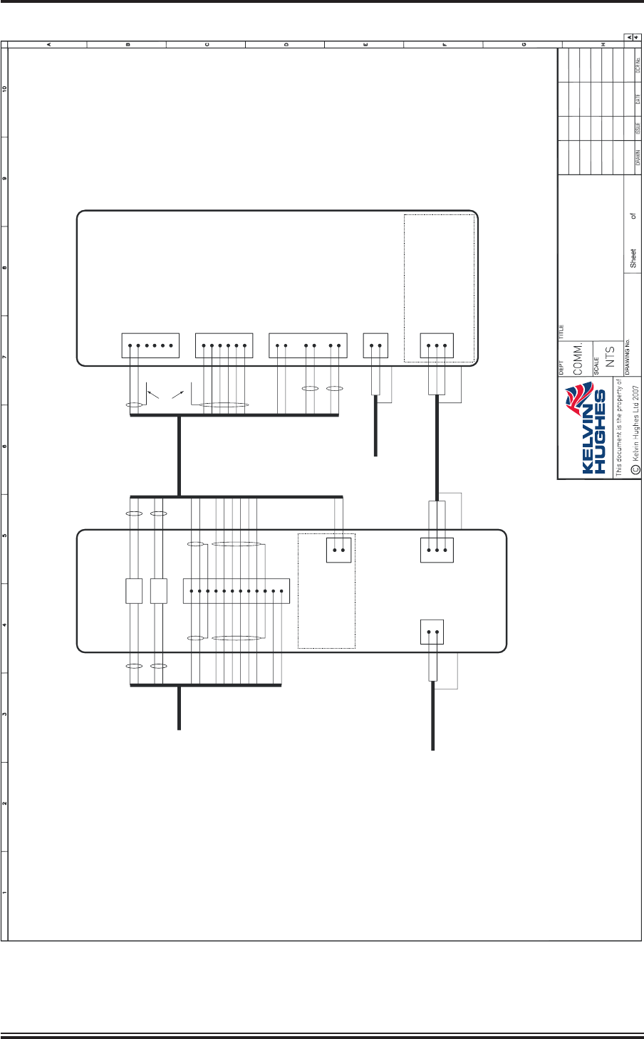
- Figure 10 - Transceiver (DTX-A3): External Connections 423
- CHAPTER 5
- CHAPTER 6
- CONTENTS
- INTRODUCTION 63
- PLANNED MAINTENANCE 63
- DIAGNOSTIC MAINTENANCE 64
- CORRECTIVE MAINTENANCE 611
- TRANSCEIVER (DTX-A3) 612
- Access 612
- Removal of Rotating Joint (45-750-0034-001) 612
- Replacement of Rotating Joint (45-750-0034-001) 613
- Removal of Gearbox and Motor (55-100-0273-001) 613
- Replacement of Gearbox and Motor (55-100-0273-001) 613
- Removal of Azimuth Encoder (GTX-A188) 613
- Replacement of Azimuth Encoder (GTX-A188) 613
- Transceiver (DTX-A115) - Removal 614
- Transceiver (DTX-A115) - Replacement 614
- Power Supply (45-690-0062-002) and PSU Sense PCB (DTX-A121) - Removal 615
- Power Supply (45-690-0062-002) and PSU Sense PCB (DTX-A121) - Replacement 615
- CAN Adapter PCB (NNR-A981) - Removal 615
- CAN Adapter PCB (NNR-A981) - Replacement 615
- SharpEye Azimuth Interface PCB (DTX-A151) - Removal 616
- SharpEye Azimuth Interface PCB (DTX-A151) - Replacement 616
- DRIVE CONTROL UNIT (GTX-A24) 618
- CHECKS AFTER UNIT REPLACEMENT 620
- TRANSCEIVER (DTX-A3) 612
- ILLUSTRATIONS
- CONTENTS
- CHAPTER 7
- INSTALLATION AND SERVICE REPORTS
KH1262
Chap ter 4
Is sue 2 Page 4.23
L
N
U
V
W
R
B
S
C
R
R
Y
B
SC
R
D
RIV
E C
O
N
T
R
O
L
UN
IT
G
T
X
-A
2
4
1
2
TB
1
TB2
1
2
3
2-C
O
R
E
P
O
W
ER
C
AB
LE
K
220
V
15
A
5
0/60H
z
1
PH
AS
E
(100m
A
E
ART
H
L
EAKAG
E)
N
O
TE:
O
N
D
R
IVE
C
O
N
TR
O
L
U
N
IT, M
AKE
LIN
KS
O
N
PLA
O
F
G
TX-
A104
AS
FO
LLO
W
S
:
LO
W SPE
ED
:
PLA-2
to
PLA-
4
H
IG
H
SPEED
: PL
A-2
to
P
LA-4
&
PLA-3
to
PL
A-4
1TB4
C
O
AX
C
O
AX
8
4
10
11
12
O
B
n
C
O
AX
ES
W
S
TO
P
R
O
C
E
SSO
R
or IN
TE
R
S
W
IT
C
H
Y
G
C
U
STO
M
C
ABLE
H
14-C
O
R
E
C
U
STO
M
C
ABL
E
H
14-C
O
R
E
O
Bn
C
O
AX
ES
W
S
O
N
/
O
FF
C
O
M
M
O
N
123
W
S
W
S
C
AN
H
I
C
AN
LO
H
L
AZ1
VID
EO
1
SYN
C
1
SC
R
SC
R
S
C
R
S
C
R
Bn/W
B/O
V
V/W
Bn
/W
B/
O
V
V
/W
nAZ1
nH
L
AZ
2
nAZ2
9
5
6
7
M
O
TO
R
S
TAR
T
+27V
M
O
TO
R
S
TAR
T
RTN
1
2
R
B
PART
O
F
P
LA
G
T
X
-A
1
0
4
VID
EO
VID
EO
(SC
R
EE
N
)
SYN
C
SYN
C
(
SC
R
EE
N
)
M
O
TO
R
S
TART
+27V
M
O
TO
R
ST
ART
RTN
R
Y
B
SC
R
L
N
C
AN
H
I
C
AN
LO
0V
G
N
D
H
L
AZ
T
R
A
N
S
CE
I
V
E
R
/G
E
A
R
B
O
X
D
T
X
-A
3
TB
2
TB3
1
2
3
4
5
6
U
V
W
TB5
1
2
5
6
1
2
3
4
M
O
TO
R
L
IN
K
S
M
U
ST
B
E
SET
FO
R
22
0V
TO
M
O
T
O
R
3-C
O
R
E
PO
W
ER
C
ABLE
L
N
O
TE
:
A
E
M
O
TOR
3
-P
H
A
S
E
2-C
O
R
E
P
O
W
ER
C
ABL
E
I
50
/60H
z,
110
V/2
20V
/1
PH
ASE
W
S(W
)
SC
R
R
B
W
S
C
O
AXES
123456
V
/W
O
B/O
V
/W
Bn
Bn
TB1
AZ2
nAZ2
AZ1
nAZ1
H
L
nH
L
S
C
R
SC
R
SC
R
E
EN
N
O
T
TE
R
M
IN
ATED
K
E
LV
IN
H
U
GHE
S
0
7
.1
2
.0
7
1
S
.R
.
1
1
Sh
ar
p
E
y
e
X-
Ba
nd
Upma
s
t
C
o
n
nec
t
io
n
s
E
H
D
-0
4
1
1
-
1
7
.0
1
.0
8
2
G
.
S
.
-
0
2
.1
0
.0
8
3
G
.S
.
-
Figure 10 - Transceiver (DTX-A3): External Connections