
User's Manual


Table Of Contents
- KH1264 ISSUE 1
- CHAPTER 1
- CHAPTER 2
- CHAPTER 3
- CONTENTS
- ILLUSTRATIONS
- Figure 1 - Transceiver (DTX-A3): Module Locations 34
- Figure 2 - Drive Control Unit (GTX-A24): Module Locations 35
- Figure 3 X-band Upmast Transceiver (DTX-A3): Functional Diagram Figure 3 38
- Figure 4 X-band Upmast Transceiver (DTX-A3): Interconnection Diagram Figure 4 39
- Figure 5 - Drive Control Unit (GTX-A24): Block Diagram 319
- CHAPTER 4
- CONTENTS
- TABLES
- ILLUSTRATIONS
- Figure 1 - Transceiver (DTX-A3): Installation Dimensions 49
- Figure 2 - Transceiver (DTX-A3): Mast Mounting 410
- Figure 3 - Transceiver (DTX-A3): Fitting Kit 411
- Figure 4 - Suggested Antenna Lifting Arrangement 412
- Figure 5 - Drive Control Unit (GTX-A24): Installation Dimensions 413
- Figure 6 - Mains Isolator: Installation Dimensions 414
- Figure 7 - Transceiver (DTX-A3): Cableform Routing 419
- Figure 8 - Drive Control Unit (GTX-A24): Cableform Routing 420
- Figure 9 - Cable Gland: Assembly 421
- Figure 10 - Transceiver (DTX-A3): External Connections 423
- CHAPTER 5
- CHAPTER 6
- CONTENTS
- INTRODUCTION 63
- PLANNED MAINTENANCE 63
- DIAGNOSTIC MAINTENANCE 64
- CORRECTIVE MAINTENANCE 611
- TRANSCEIVER (DTX-A3) 612
- Access 612
- Removal of Rotating Joint (45-750-0034-001) 612
- Replacement of Rotating Joint (45-750-0034-001) 613
- Removal of Gearbox and Motor (55-100-0273-001) 613
- Replacement of Gearbox and Motor (55-100-0273-001) 613
- Removal of Azimuth Encoder (GTX-A188) 613
- Replacement of Azimuth Encoder (GTX-A188) 613
- Transceiver (DTX-A115) - Removal 614
- Transceiver (DTX-A115) - Replacement 614
- Power Supply (45-690-0062-002) and PSU Sense PCB (DTX-A121) - Removal 615
- Power Supply (45-690-0062-002) and PSU Sense PCB (DTX-A121) - Replacement 615
- CAN Adapter PCB (NNR-A981) - Removal 615
- CAN Adapter PCB (NNR-A981) - Replacement 615
- SharpEye Azimuth Interface PCB (DTX-A151) - Removal 616
- SharpEye Azimuth Interface PCB (DTX-A151) - Replacement 616
- DRIVE CONTROL UNIT (GTX-A24) 618
- CHECKS AFTER UNIT REPLACEMENT 620
- TRANSCEIVER (DTX-A3) 612
- ILLUSTRATIONS
- CONTENTS
- CHAPTER 7
- INSTALLATION AND SERVICE REPORTS
KH1264
Chap ter 4
Is sue 2 Page 4.21
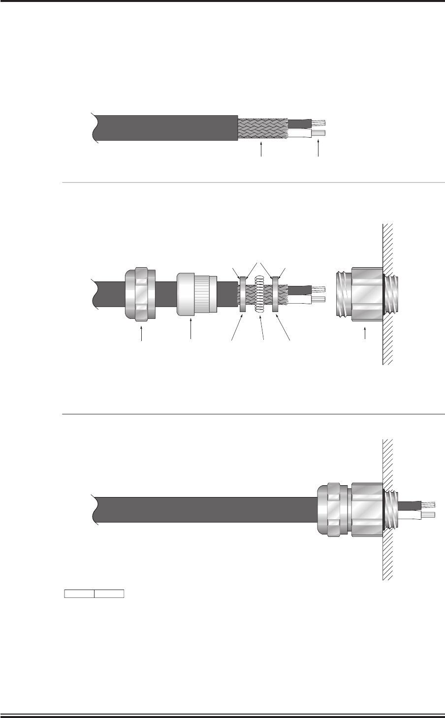
RECESSED
SIDE (TO ALLOW
FOR SPRING)
FLAT
SIDE
FLAT
SIDE
PREPARE CABLE
(LENGTHS OF CORES AND SCREEN TO BE CUT TO SUIT APPLICATION)
ASSEMBLE GLAND AS SHOWN
ASSEMBLED GLAND
UNIT CASING
PRESSURE
SCREW
SEALING
INSERT
RECESSED
WASHER
RECESSED
WASHER
CIRCULAR
SPRING
GLAND
BODY
CD-7028
ISSUE 1
BRAIDED SCREEN CABLE CORES
THE BRAIDED SCREEN IS BONDED BY A CIRCULAR SPRING BETWEEN THE TWO RECESSED WASHERS.
THE CABLE GLAND’S SEALING INSERT PRESSES ON THE WASHERS. WHEN THE PRESSURE SCREW
IS TIGHTENED UP IT COMPRESSES THE SPRING TIGHTLY AROUND THE SCREEN;
AT THE SAME TIME THE SEALING INSERT BONDS THE SCREW WITH THE GLAND BODY.
NOTE:
Figure 9 - Cable Gland: Assembly