
User's Manual


Table Of Contents
- KH1264 ISSUE 1
- CHAPTER 1
- CHAPTER 2
- CHAPTER 3
- CONTENTS
- ILLUSTRATIONS
- Figure 1 - Transceiver (DTX-A3): Module Locations 34
- Figure 2 - Drive Control Unit (GTX-A24): Module Locations 35
- Figure 3 X-band Upmast Transceiver (DTX-A3): Functional Diagram Figure 3 38
- Figure 4 X-band Upmast Transceiver (DTX-A3): Interconnection Diagram Figure 4 39
- Figure 5 - Drive Control Unit (GTX-A24): Block Diagram 319
- CHAPTER 4
- CONTENTS
- TABLES
- ILLUSTRATIONS
- Figure 1 - Transceiver (DTX-A3): Installation Dimensions 49
- Figure 2 - Transceiver (DTX-A3): Mast Mounting 410
- Figure 3 - Transceiver (DTX-A3): Fitting Kit 411
- Figure 4 - Suggested Antenna Lifting Arrangement 412
- Figure 5 - Drive Control Unit (GTX-A24): Installation Dimensions 413
- Figure 6 - Mains Isolator: Installation Dimensions 414
- Figure 7 - Transceiver (DTX-A3): Cableform Routing 419
- Figure 8 - Drive Control Unit (GTX-A24): Cableform Routing 420
- Figure 9 - Cable Gland: Assembly 421
- Figure 10 - Transceiver (DTX-A3): External Connections 423
- CHAPTER 5
- CHAPTER 6
- CONTENTS
- INTRODUCTION 63
- PLANNED MAINTENANCE 63
- DIAGNOSTIC MAINTENANCE 64
- CORRECTIVE MAINTENANCE 611
- TRANSCEIVER (DTX-A3) 612
- Access 612
- Removal of Rotating Joint (45-750-0034-001) 612
- Replacement of Rotating Joint (45-750-0034-001) 613
- Removal of Gearbox and Motor (55-100-0273-001) 613
- Replacement of Gearbox and Motor (55-100-0273-001) 613
- Removal of Azimuth Encoder (GTX-A188) 613
- Replacement of Azimuth Encoder (GTX-A188) 613
- Transceiver (DTX-A115) - Removal 614
- Transceiver (DTX-A115) - Replacement 614
- Power Supply (45-690-0062-002) and PSU Sense PCB (DTX-A121) - Removal 615
- Power Supply (45-690-0062-002) and PSU Sense PCB (DTX-A121) - Replacement 615
- CAN Adapter PCB (NNR-A981) - Removal 615
- CAN Adapter PCB (NNR-A981) - Replacement 615
- SharpEye Azimuth Interface PCB (DTX-A151) - Removal 616
- SharpEye Azimuth Interface PCB (DTX-A151) - Replacement 616
- DRIVE CONTROL UNIT (GTX-A24) 618
- CHECKS AFTER UNIT REPLACEMENT 620
- TRANSCEIVER (DTX-A3) 612
- ILLUSTRATIONS
- CONTENTS
- CHAPTER 7
- INSTALLATION AND SERVICE REPORTS
14 Core Com pos ite Ca ble
34 The 14-core composite cable (KH code number 45-762-0116-001) is a Low Smoke and
Fume cable, but not Zero Halogen, made for Kelvin Hughes and comprises the
following:
(1) Core function:
4 cores of 32/0.2 mm (1.0 mm
2
) copper wire.
1 screened twisted pair 16/0.2 mm (0.5 mm
2
) copper wire for serial data links.
3 twisted pairs in 1 screen 16/0.2 mm (0.5 mm
2
) copper wire for serial data
links.
2 cores of co-axial cable 7/0.25 mm (0.35 mm
2
).
(2) Overall Screen
The cable has an overall screen of close woven copper braid (tinned copper
91% minimum coverage) suitable for a high noise environment.
(3) Outer Sheath
The cable has a black outer sheath to withstand exposure to the outside
environment, of salt air, rain, lubricating or diesel oil splashes, sun, snow, ice
and some possible abrasion. The outer sheath is UV stable.
(4) Conductor rating:
1.0 mm
2
0.5 mm
2
Coaxial
DC between conductors 100 V 30 V 15 V
DC current 100 mA 50 mA
Impedance 75 W
Losses <3 dB at 25 MHz
up to 60 m
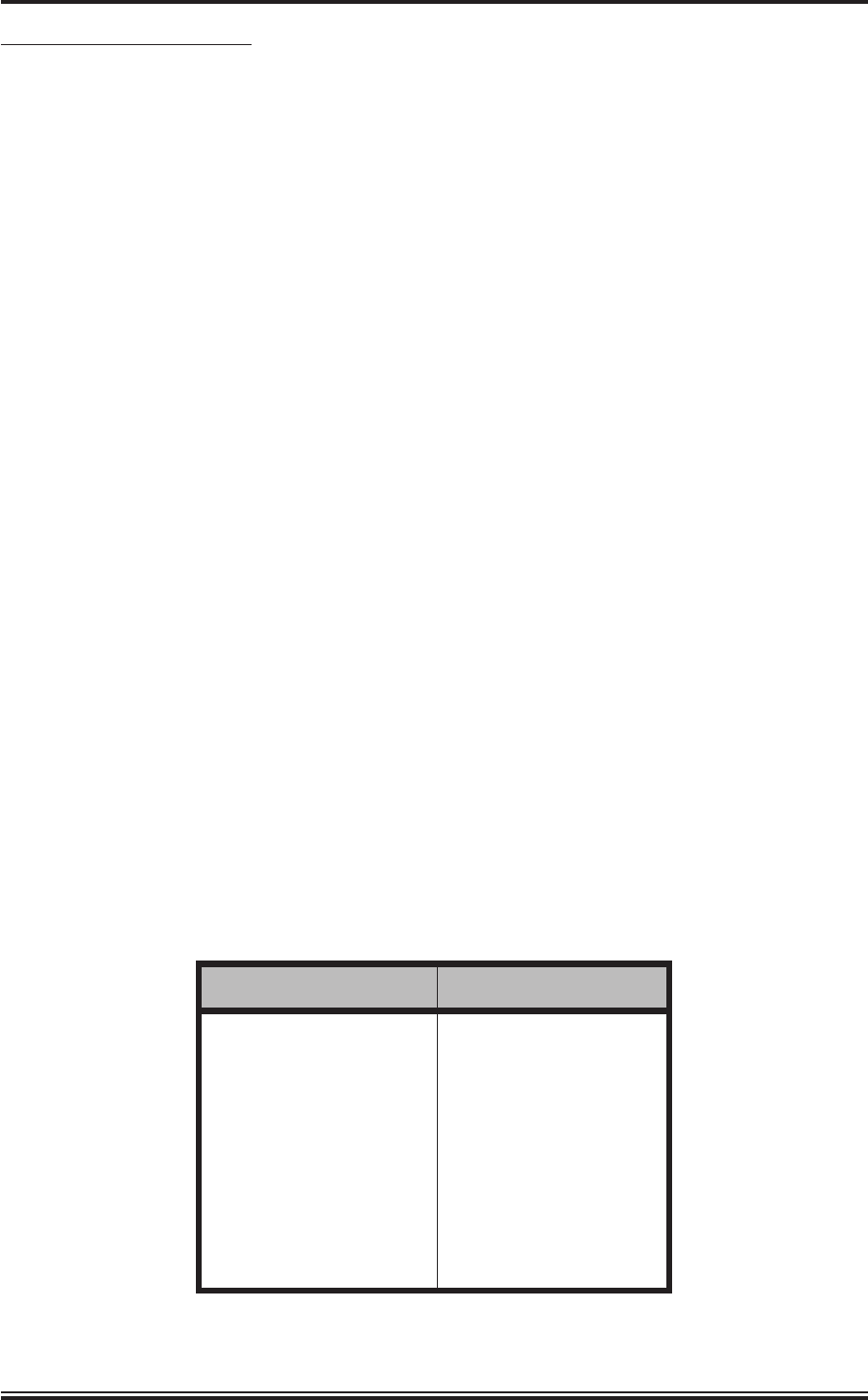
TABLE 2: 14-Core Cable Colour Abbreviations
ABBREVIATION COLOUR
R RED
B BLUE
G GREEN
Y YELLOW
BN BROWN
V VIOLET
O ORANGE
W WHITE
S SLATE (GREY)
KH1264
Chap ter 4
Page 4.16 Is sue 2