
User's Manual


Table Of Contents
- KH1264 ISSUE 1
- CHAPTER 1
- CHAPTER 2
- CHAPTER 3
- CONTENTS
- ILLUSTRATIONS
- Figure 1 - Transceiver (DTX-A3): Module Locations 34
- Figure 2 - Drive Control Unit (GTX-A24): Module Locations 35
- Figure 3 X-band Upmast Transceiver (DTX-A3): Functional Diagram Figure 3 38
- Figure 4 X-band Upmast Transceiver (DTX-A3): Interconnection Diagram Figure 4 39
- Figure 5 - Drive Control Unit (GTX-A24): Block Diagram 319
- CHAPTER 4
- CONTENTS
- TABLES
- ILLUSTRATIONS
- Figure 1 - Transceiver (DTX-A3): Installation Dimensions 49
- Figure 2 - Transceiver (DTX-A3): Mast Mounting 410
- Figure 3 - Transceiver (DTX-A3): Fitting Kit 411
- Figure 4 - Suggested Antenna Lifting Arrangement 412
- Figure 5 - Drive Control Unit (GTX-A24): Installation Dimensions 413
- Figure 6 - Mains Isolator: Installation Dimensions 414
- Figure 7 - Transceiver (DTX-A3): Cableform Routing 419
- Figure 8 - Drive Control Unit (GTX-A24): Cableform Routing 420
- Figure 9 - Cable Gland: Assembly 421
- Figure 10 - Transceiver (DTX-A3): External Connections 423
- CHAPTER 5
- CHAPTER 6
- CONTENTS
- INTRODUCTION 63
- PLANNED MAINTENANCE 63
- DIAGNOSTIC MAINTENANCE 64
- CORRECTIVE MAINTENANCE 611
- TRANSCEIVER (DTX-A3) 612
- Access 612
- Removal of Rotating Joint (45-750-0034-001) 612
- Replacement of Rotating Joint (45-750-0034-001) 613
- Removal of Gearbox and Motor (55-100-0273-001) 613
- Replacement of Gearbox and Motor (55-100-0273-001) 613
- Removal of Azimuth Encoder (GTX-A188) 613
- Replacement of Azimuth Encoder (GTX-A188) 613
- Transceiver (DTX-A115) - Removal 614
- Transceiver (DTX-A115) - Replacement 614
- Power Supply (45-690-0062-002) and PSU Sense PCB (DTX-A121) - Removal 615
- Power Supply (45-690-0062-002) and PSU Sense PCB (DTX-A121) - Replacement 615
- CAN Adapter PCB (NNR-A981) - Removal 615
- CAN Adapter PCB (NNR-A981) - Replacement 615
- SharpEye Azimuth Interface PCB (DTX-A151) - Removal 616
- SharpEye Azimuth Interface PCB (DTX-A151) - Replacement 616
- DRIVE CONTROL UNIT (GTX-A24) 618
- CHECKS AFTER UNIT REPLACEMENT 620
- TRANSCEIVER (DTX-A3) 612
- ILLUSTRATIONS
- CONTENTS
- CHAPTER 7
- INSTALLATION AND SERVICE REPORTS
DRIVE CON TROL UNIT (GTX-A24)
WARNING
ENSURE THAT ALL POWER SUPPLIES IN THE VICINITY OF THE DRIVE
CONTROL UNIT ARE ISOLATED BEFORE ANY INSTALLATION TAKES
PLACE.
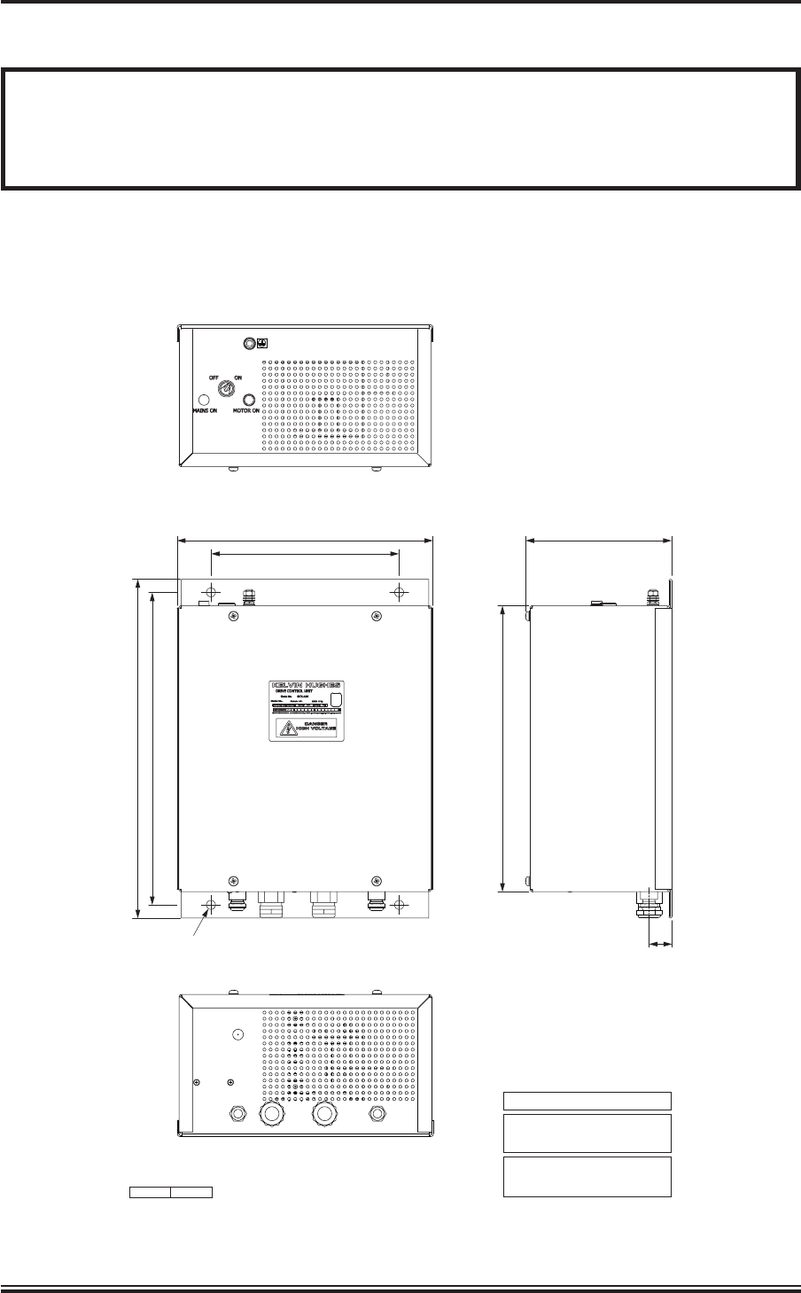
30 Fit the drive control unit to the securing bulkhead using the installation bolts supplied
with the fitting kit. Refer to Figure 5 for dimensions. Allow sufficient space at the base of
the unit to allow the cables to be inserted through the cable glands and at the top of the unit for
withdrawal of the key from the keyswitch.
KH1264
Chap ter 4
Is sue 2 Page 4.13
Ø12 FIXING HOLE
4 POSITIONS
450
415 (FIXING CENTRES)
380
340
250 (FIXING CENTRES)
30.5
CD-7022
ISSUE 3
ALL DIMENSIONS IN MILLIMETRES UNLESS OTHERWISE STATED
WEIGHT: 11kg
COMPASS SAFE DISTANCES:
OPERATIONAL TEMPERATURE RANGE:
AT 0% RELATIVE HUMIDITY -15°C to +55°C
AT 95% RELATIVE HUMIDITY +40°C
GRADE I STANDARD COMPASS 2.46m
GRADE II STEERING COMPASS 1.54m
194
Figure 5 - Drive Control Unit (GTX-A24): Installation Dimensions