
User's Manual


Table Of Contents
- KH1264 ISSUE 1
- CHAPTER 1
- CHAPTER 2
- CHAPTER 3
- CONTENTS
- ILLUSTRATIONS
- Figure 1 - Transceiver (DTX-A3): Module Locations 34
- Figure 2 - Drive Control Unit (GTX-A24): Module Locations 35
- Figure 3 X-band Upmast Transceiver (DTX-A3): Functional Diagram Figure 3 38
- Figure 4 X-band Upmast Transceiver (DTX-A3): Interconnection Diagram Figure 4 39
- Figure 5 - Drive Control Unit (GTX-A24): Block Diagram 319
- CHAPTER 4
- CONTENTS
- TABLES
- ILLUSTRATIONS
- Figure 1 - Transceiver (DTX-A3): Installation Dimensions 49
- Figure 2 - Transceiver (DTX-A3): Mast Mounting 410
- Figure 3 - Transceiver (DTX-A3): Fitting Kit 411
- Figure 4 - Suggested Antenna Lifting Arrangement 412
- Figure 5 - Drive Control Unit (GTX-A24): Installation Dimensions 413
- Figure 6 - Mains Isolator: Installation Dimensions 414
- Figure 7 - Transceiver (DTX-A3): Cableform Routing 419
- Figure 8 - Drive Control Unit (GTX-A24): Cableform Routing 420
- Figure 9 - Cable Gland: Assembly 421
- Figure 10 - Transceiver (DTX-A3): External Connections 423
- CHAPTER 5
- CHAPTER 6
- CONTENTS
- INTRODUCTION 63
- PLANNED MAINTENANCE 63
- DIAGNOSTIC MAINTENANCE 64
- CORRECTIVE MAINTENANCE 611
- TRANSCEIVER (DTX-A3) 612
- Access 612
- Removal of Rotating Joint (45-750-0034-001) 612
- Replacement of Rotating Joint (45-750-0034-001) 613
- Removal of Gearbox and Motor (55-100-0273-001) 613
- Replacement of Gearbox and Motor (55-100-0273-001) 613
- Removal of Azimuth Encoder (GTX-A188) 613
- Replacement of Azimuth Encoder (GTX-A188) 613
- Transceiver (DTX-A115) - Removal 614
- Transceiver (DTX-A115) - Replacement 614
- Power Supply (45-690-0062-002) and PSU Sense PCB (DTX-A121) - Removal 615
- Power Supply (45-690-0062-002) and PSU Sense PCB (DTX-A121) - Replacement 615
- CAN Adapter PCB (NNR-A981) - Removal 615
- CAN Adapter PCB (NNR-A981) - Replacement 615
- SharpEye Azimuth Interface PCB (DTX-A151) - Removal 616
- SharpEye Azimuth Interface PCB (DTX-A151) - Replacement 616
- DRIVE CONTROL UNIT (GTX-A24) 618
- CHECKS AFTER UNIT REPLACEMENT 620
- TRANSCEIVER (DTX-A3) 612
- ILLUSTRATIONS
- CONTENTS
- CHAPTER 7
- INSTALLATION AND SERVICE REPORTS
KH1264
Chap ter 4
Page 4.10 Is sue 2
CD-7032
ISSUE 1
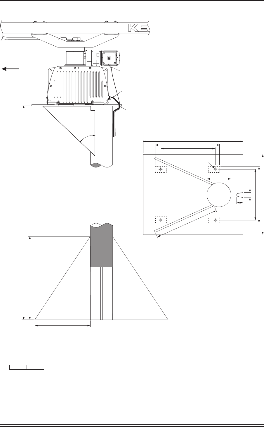
MOUNTING PLATE & STIFFENING PIECES
15mm STEEL
FWD
TUBE THICKNESS
12mm MINIMUM
500
MAX 2m
750
4 x FIXING HOLES Ø17
540
830
460
460
474
200
50
30
674
4
9
0
450
3-CORE MOTOR POWER CABLE TO MOTOR
14-CORE & 2-CORE CABLES FED THROUGH
CABLE GLANDS AT REAR OF CASE
CABLES FED THROUGH NOTCH
IN MOUNTING PLATE
TUBE DIAMETER
200mm MINIMUM
ALL DIMENSIONS IN MILLIMETRES UNLESS OTHERWISE STATED
DO NOT LIFT HERE
Figure 2 - Transceiver (DTX-A3): Mast Mounting