
User's Manual


Table Of Contents
- KH1264 ISSUE 1
- CHAPTER 1
- CHAPTER 2
- CHAPTER 3
- CONTENTS
- ILLUSTRATIONS
- Figure 1 - Transceiver (DTX-A3): Module Locations 34
- Figure 2 - Drive Control Unit (GTX-A24): Module Locations 35
- Figure 3 X-band Upmast Transceiver (DTX-A3): Functional Diagram Figure 3 38
- Figure 4 X-band Upmast Transceiver (DTX-A3): Interconnection Diagram Figure 4 39
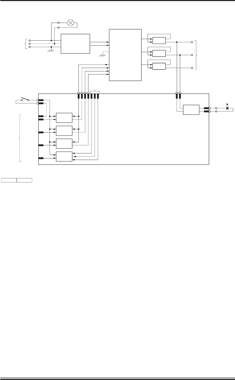
- Figure 5 - Drive Control Unit (GTX-A24): Block Diagram 319
- CHAPTER 4
- CONTENTS
- TABLES
- ILLUSTRATIONS
- Figure 1 - Transceiver (DTX-A3): Installation Dimensions 49
- Figure 2 - Transceiver (DTX-A3): Mast Mounting 410
- Figure 3 - Transceiver (DTX-A3): Fitting Kit 411
- Figure 4 - Suggested Antenna Lifting Arrangement 412
- Figure 5 - Drive Control Unit (GTX-A24): Installation Dimensions 413
- Figure 6 - Mains Isolator: Installation Dimensions 414
- Figure 7 - Transceiver (DTX-A3): Cableform Routing 419
- Figure 8 - Drive Control Unit (GTX-A24): Cableform Routing 420
- Figure 9 - Cable Gland: Assembly 421
- Figure 10 - Transceiver (DTX-A3): External Connections 423
- CHAPTER 5
- CHAPTER 6
- CONTENTS
- INTRODUCTION 63
- PLANNED MAINTENANCE 63
- DIAGNOSTIC MAINTENANCE 64
- CORRECTIVE MAINTENANCE 611
- TRANSCEIVER (DTX-A3) 612
- Access 612
- Removal of Rotating Joint (45-750-0034-001) 612
- Replacement of Rotating Joint (45-750-0034-001) 613
- Removal of Gearbox and Motor (55-100-0273-001) 613
- Replacement of Gearbox and Motor (55-100-0273-001) 613
- Removal of Azimuth Encoder (GTX-A188) 613
- Replacement of Azimuth Encoder (GTX-A188) 613
- Transceiver (DTX-A115) - Removal 614
- Transceiver (DTX-A115) - Replacement 614
- Power Supply (45-690-0062-002) and PSU Sense PCB (DTX-A121) - Removal 615
- Power Supply (45-690-0062-002) and PSU Sense PCB (DTX-A121) - Replacement 615
- CAN Adapter PCB (NNR-A981) - Removal 615
- CAN Adapter PCB (NNR-A981) - Replacement 615
- SharpEye Azimuth Interface PCB (DTX-A151) - Removal 616
- SharpEye Azimuth Interface PCB (DTX-A151) - Replacement 616
- DRIVE CONTROL UNIT (GTX-A24) 618
- CHECKS AFTER UNIT REPLACEMENT 620
- TRANSCEIVER (DTX-A3) 612
- ILLUSTRATIONS
- CONTENTS
- CHAPTER 7
- INSTALLATION AND SERVICE REPORTS
KH1264
Chap ter 3
Is sue 2 Page 3.19
CD-7279
ISSUE 1
MAINS FILTER
45-680-0028-001
L1
L
N
E
L
N
TB1
220V MAINS
INPUT
1
2
3
LIVE
NEUTRAL
EARTH
TB3
1
2
MAINS ON
LP1
INVERTER
45-690-0033-001
L1
L1
L2
L3(N) NOT USED
PE
T1
L2
TB2
1
2
3
220V 3 PHASE OUTPUT
TO MOTOR
L3
L4
T2
T3
COMMON
FORWARD
SPEED 1
SPEED 2
NOT
USED
1
2
3
4
6
7
8
PLB
P15
F
S1
S2
+15V O/P
FORWARD
SPEED 1
SPEED 2
FERRITE CORES
(2 TURNS THROUGH
EACH RING)
PLD
3
1
PLC
2
1
LED
DRIVER
TB3
3
4
OPTO-
ISOLATOR
DRIVE INTERFACE PCB
GTX-A104
OPTO-
ISOLATOR
OPTO-
ISOLATOR
OPTO-
ISOLATOR
+V
F ADJUST
-V
PLC
6
5
PLA
1
2
3
4
5
START (27V)
START (RTN)
SPEED 1
SPEED 2
SPEED 3
Tx CONTROL
KEYSWITCH
SW1
MOTOR ON
D1
NOTE: TAGBLOCK 1TB4 AND COAX CONNECTORS NOT SHOWN
Figure 5 - Drive Control Unit (GTX-A24): Block Diagram