
User's Manual


Table Of Contents
- KH1264 ISSUE 1
- CHAPTER 1
- CHAPTER 2
- CHAPTER 3
- CONTENTS
- ILLUSTRATIONS
- Figure 1 - Transceiver (DTX-A3): Module Locations 34
- Figure 2 - Drive Control Unit (GTX-A24): Module Locations 35
- Figure 3 X-band Upmast Transceiver (DTX-A3): Functional Diagram Figure 3 38
- Figure 4 X-band Upmast Transceiver (DTX-A3): Interconnection Diagram Figure 4 39
- Figure 5 - Drive Control Unit (GTX-A24): Block Diagram 319
- CHAPTER 4
- CONTENTS
- TABLES
- ILLUSTRATIONS
- Figure 1 - Transceiver (DTX-A3): Installation Dimensions 49
- Figure 2 - Transceiver (DTX-A3): Mast Mounting 410
- Figure 3 - Transceiver (DTX-A3): Fitting Kit 411
- Figure 4 - Suggested Antenna Lifting Arrangement 412
- Figure 5 - Drive Control Unit (GTX-A24): Installation Dimensions 413
- Figure 6 - Mains Isolator: Installation Dimensions 414
- Figure 7 - Transceiver (DTX-A3): Cableform Routing 419
- Figure 8 - Drive Control Unit (GTX-A24): Cableform Routing 420
- Figure 9 - Cable Gland: Assembly 421
- Figure 10 - Transceiver (DTX-A3): External Connections 423
- CHAPTER 5
- CHAPTER 6
- CONTENTS
- INTRODUCTION 63
- PLANNED MAINTENANCE 63
- DIAGNOSTIC MAINTENANCE 64
- CORRECTIVE MAINTENANCE 611
- TRANSCEIVER (DTX-A3) 612
- Access 612
- Removal of Rotating Joint (45-750-0034-001) 612
- Replacement of Rotating Joint (45-750-0034-001) 613
- Removal of Gearbox and Motor (55-100-0273-001) 613
- Replacement of Gearbox and Motor (55-100-0273-001) 613
- Removal of Azimuth Encoder (GTX-A188) 613
- Replacement of Azimuth Encoder (GTX-A188) 613
- Transceiver (DTX-A115) - Removal 614
- Transceiver (DTX-A115) - Replacement 614
- Power Supply (45-690-0062-002) and PSU Sense PCB (DTX-A121) - Removal 615
- Power Supply (45-690-0062-002) and PSU Sense PCB (DTX-A121) - Replacement 615
- CAN Adapter PCB (NNR-A981) - Removal 615
- CAN Adapter PCB (NNR-A981) - Replacement 615
- SharpEye Azimuth Interface PCB (DTX-A151) - Removal 616
- SharpEye Azimuth Interface PCB (DTX-A151) - Replacement 616
- DRIVE CONTROL UNIT (GTX-A24) 618
- CHECKS AFTER UNIT REPLACEMENT 620
- TRANSCEIVER (DTX-A3) 612
- ILLUSTRATIONS
- CONTENTS
- CHAPTER 7
- INSTALLATION AND SERVICE REPORTS
FUNC TIONAL DE SCRIP TION
6 Functional diagrams of the transceiver and antenna are shown in Figure 3 and the
interconnections in Figure 4.
TRANSCEIVER
Mo tor and Gearbox
7 The antenna motor is driven by a 3 phase supply from the inverter in the Drive Control
Unit. The Drive Control Unit is configured to provide a soft start and a soft stop for the
motor, so that the motor takes a few seconds to reach normal antenna rotation speed and a few
seconds to slow down when stopped. This reduces the start up and stopping torque on the motor.
The motor is connected to the antenna by the gearbox which provides the drive to the antenna.
8 The Azimuth and Heading Line pulses are generated by the Azimuth Encoder, which is
mounted on the output shaft of the gearbox. Part of the Azimuth Encoder rotates with the
gearbox and part remains stationary with the enclosure. The Azimuth Encoder uses an optical
disc with sensors.
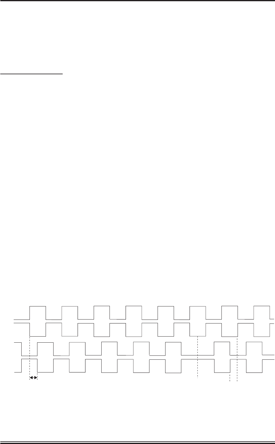
9 Two heading line pulses (heading line and inverse heading line) and two sets of 1024
pulses per revolution azimuth pulses (each set comprising azimuth and inverse azimuth)
are produced for each rotation of the antenna. The two sets of azimuth pulses are produced in
quadrature (called Q1 and Q2 pulses), with Q2 lagging Q1 pulses by 90° when the antenna
rotates in the normal direction. This allows the azimuth data to be used to detect reverse rotation
of the antenna (which may occur due to windage when the motor is switched off) as Q2 pulses
lead Q1 pulses by 90° when the antenna starts to rotate in the reverse direction. The Azimuth
Encoder is supplied with +15 V, which is used to generate azimuth and heading line output
pulses of +15 V. The pulses are passed directly to the display system via TB1 and also to the
SharpEye
TM
Azimuth Interface PCA (DTX-A151), which opto-isolates the signals before they
are routed to the Transceiver (DTX-A115).
10 The phase of the azimuth inputs for normal and reverse rotation is shown below.
KH1264
Chap ter 3
Page 3.6 Is sue 2
Q1
Q3
Q2
Q4
Q2 TO Q1
90 DEGREE
PHASE LAG
Q2 TO Q1
90 DEGREE
PHASE LEAD
ANTENNA
DIRECTION
REVERSES