
User's Manual

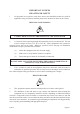
Table Of Contents
- KH1264 ISSUE 1
- CHAPTER 1
- CHAPTER 2
- CHAPTER 3
- CONTENTS
- ILLUSTRATIONS
- Figure 1 - Transceiver (DTX-A3): Module Locations 34
- Figure 2 - Drive Control Unit (GTX-A24): Module Locations 35
- Figure 3 X-band Upmast Transceiver (DTX-A3): Functional Diagram Figure 3 38
- Figure 4 X-band Upmast Transceiver (DTX-A3): Interconnection Diagram Figure 4 39
- Figure 5 - Drive Control Unit (GTX-A24): Block Diagram 319
- CHAPTER 4
- CONTENTS
- TABLES
- ILLUSTRATIONS
- Figure 1 - Transceiver (DTX-A3): Installation Dimensions 49
- Figure 2 - Transceiver (DTX-A3): Mast Mounting 410
- Figure 3 - Transceiver (DTX-A3): Fitting Kit 411
- Figure 4 - Suggested Antenna Lifting Arrangement 412
- Figure 5 - Drive Control Unit (GTX-A24): Installation Dimensions 413
- Figure 6 - Mains Isolator: Installation Dimensions 414
- Figure 7 - Transceiver (DTX-A3): Cableform Routing 419
- Figure 8 - Drive Control Unit (GTX-A24): Cableform Routing 420
- Figure 9 - Cable Gland: Assembly 421
- Figure 10 - Transceiver (DTX-A3): External Connections 423
- CHAPTER 5
- CHAPTER 6
- CONTENTS
- INTRODUCTION 63
- PLANNED MAINTENANCE 63
- DIAGNOSTIC MAINTENANCE 64
- CORRECTIVE MAINTENANCE 611
- TRANSCEIVER (DTX-A3) 612
- Access 612
- Removal of Rotating Joint (45-750-0034-001) 612
- Replacement of Rotating Joint (45-750-0034-001) 613
- Removal of Gearbox and Motor (55-100-0273-001) 613
- Replacement of Gearbox and Motor (55-100-0273-001) 613
- Removal of Azimuth Encoder (GTX-A188) 613
- Replacement of Azimuth Encoder (GTX-A188) 613
- Transceiver (DTX-A115) - Removal 614
- Transceiver (DTX-A115) - Replacement 614
- Power Supply (45-690-0062-002) and PSU Sense PCB (DTX-A121) - Removal 615
- Power Supply (45-690-0062-002) and PSU Sense PCB (DTX-A121) - Replacement 615
- CAN Adapter PCB (NNR-A981) - Removal 615
- CAN Adapter PCB (NNR-A981) - Replacement 615
- SharpEye Azimuth Interface PCB (DTX-A151) - Removal 616
- SharpEye Azimuth Interface PCB (DTX-A151) - Replacement 616
- DRIVE CONTROL UNIT (GTX-A24) 618
- CHECKS AFTER UNIT REPLACEMENT 620
- TRANSCEIVER (DTX-A3) 612
- ILLUSTRATIONS
- CONTENTS
- CHAPTER 7
- INSTALLATION AND SERVICE REPORTS

RA DI A TION HAZ ARD: NON-ION ISING
AERIAL RADIATION HAZARD: INJURY CAN RESULT FROM EXPOSURE TO
THE MAIN BEAM OF A STATIONARY RADAR AERIAL. DO NOT STAND
LESS THAN 2 m FROM THE CENTRAL FRONT FACE OF THE AERIAL.
6 It is accepted in most countries that no significant hazard is presented by radio frequency
mean power density levels up to 10mW/cm. RF power levels in excess of this may cause
harmful effects, particularly to the eyes.
7 Users of cardiac pacemakers should be aware that radio frequency transmissions, can
damage some such devices or cause irregularities in their operation. Persons using a
pacemaker should ascertain whether their device is likely to be affected before exposing
themselves to the risk of malfunction.
SAFETY ALOFT
AERIAL ROTATION: BEFORE MAINTENANCE TO THE TURNING
MECHANISM TAKES PLACE, DISABLE AERIAL ROTATION.
8 When working aloft, ensure that it is brought to the attention of someone in authority at
deck or at ground level and that suitably placed warning notices are posted warning that
work aloft is in progress. Ensure that the means of access aloft is secure and beware of wet or
slippery ladder rungs and working areas.
9 When working on or near a radar scanner and other moving or r.f. radiating equipment,
ensure that it is switched off and that the fuses have been removed and retained.
PER SONAL PRO TEC TION
10 Personal protection must be used whenever the possibility of an uncontrolled hazard
exists. For example, a suitable face visor, gloves and a body apron should be worn when
handling cathode ray tubes, as a precaution against injury in the event of breakage.
EQUIP MENT SAFETY
11 Do not run the radar with the rotating joint output disconnected.
12 Removal of printed circuit boards with power connected can damage FETs and
Integrated Circuits.
13 The circuitry used on the equipment PCBs utilises CMOS Integrated Circuits. All the
relevant CMOS precautions must be taken to avoid damage to CMOS circuitry when any
board is removed.
14 The equipment should be serviced by qualified agents only.
Page x Is sue 2