
Instruction Manual

5
2. General safety warnings
The current national regulations on
accident prevention and workplace
safety must be followed whenever
work is carried out. Internal regula-
tions issued by the operator must be
followed, even if they are not men-
tioned in these instructions.
Never use the low pressure calibra-
tor together with an external pressure
source.
Do not remove any connected compo-
nents (e.g. test objects) when the low
pressure calibrator is under pressure.
Open the pressure relief valve before
removing one of the parts.
Only use the adapters and seals that
are available as accessories.
Do not store the calibrator under pres-
sure: only store the low pressure cali-
brator with the pressure relief valve
open.
Avoid the action of force of any kind
on the low pressure calibrator and its
operating controls.
Do not use low pressure calibrators if
they are damaged or faulty.
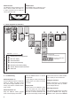
3. Operating the LPX calibrator
Operating the pressure calibrator is de
-
scribed starting on page 16.
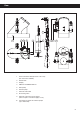
Connect the test object
You can connect your test object to the
low pressure calibrator via the pressure
connection (9).
Zeroing the device
Engage the hand pump (5) in the con
-
nection port (10). Open the pressure
relief valve (until the red mark is visible
at most) to release any pressure that
may be present. If the pressure display
does not show zero, perform a zeroing
procedure
(Set Zero)
. Then close the
pressure relief valve.
Pressure generation
You can use the hand pump (5) to make
an approximate setting for the desired
pressure.
Generating negative pressure
(vacuum)
Engage the vacuum pump (6) in the
connection port (10) and lower the
pressure. You can then ne-tune the
pressure by screwing the ne-tuning
valve (8) in or out.
Release pressure
Open the relief valve (7) to reduce the
pressure to an approximate level, or to
vent the low pressure calibrator.
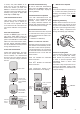
Information about the display
If no pressure can be shown on the
display, it will show
OFL(overow)or
UFL(underow).
If pressure outside the device’s
measuring range is applied, the
last valid pressure value that was
measured will ash on the display
(overload warning).
Display
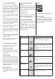
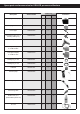
4. Description of the functions
Menu navigation
If the selected function or unit is not
activated
by pressing the ENTER
button within 5 seconds, the display
will return to measuring mode without
changing a setting.
Function
Display
Description
Min. / max. display Shows the peak and trough pressure values
measured thus far.
(Display is shown with reduced resolution)
Leak measurement Leak mode is used to determine the pressure
change over a dened period, which can be
changed.
(Leak measurement period, factory setting:
10 minutes)
Zero the display
Permanently sets the applied pressure as the new
pressure zero point.
Reset
display
Resets the pressure zero point to the factory set-
ting.
(Zero point for vacuum ➞ absolute pressure is
displayed)
Automatic
switch-off function
(Cont = Continuous) The device switches off
automatically after a dened period (which can
be changed), starting from the last time a button
was pressed. (Switch-off period, factory setting:
15 minutes)
Select units
mbar, bar, hPa, kPa, MPa, cmH2O, mH2O, inH2O,
ftH2O, PSI, kp/cm
2
, mmHg, inHg