
Datasheet


in the design. You can easily zoom and pan to any area on the
waveform to examine the details of these individual occurrences.
You can also enable horizontal and vertical cursors for further
analysis. See the Appendix for programming examples on analog
edge trigger.
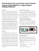
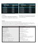
Figure 4a. A complete capture of buck converter power-up with soft-
start sequence.
Figure 4b. Panning and zooming into the soft-start behavior (top) and output
voltage overshoot before reaching steady state (bottom).
Simultaneous Voltage and Current
Measurement Using Two Model DMM7510s
The Model DMM7510 is a very powerful high-end multimeter
packed with sophisticated modern technologies. The next
demonstration explores the advanced instrument programming
and integration valuable to applications seeking simultaneous
voltage and/or current digitizing solutions.
The buck converter power-up transient analysis can be more
involved than merely monitoring the output voltage. The input
voltage, input current, output voltage, and load current are all
signals of importance. The key is to synchronize these signals to
a single triggering event to uncover critical information of about
the design of the buck converter. The example below uses two
Model DMM7510s to demonstrate this capability.
Connecting two Model DMM7510s to monitor two different
signals on the buck converter simply involves connecting each
standard pair of test leads from the circuit to each DMM. A
TSP-Link
®
cross-over cable is used to daisy-chain the two DMMs
together for synchronizing the analog waveform trigger event on
both. Keithley Instruments’ TSP-Link
®
interface is a high-speed
trigger synchronization and communication bus that test system
builders can use to connect multiple instruments in a master and
subordinate configuration. Once connected, all the instruments
in this system can be programmed (using TSP commands only)
and operated under the control of the master instrument.
This allows the instruments to run tests more quickly because
they can be decoupled from frequent computer interaction.
Furthermore, multiple instruments are used as if they are part of
the same physical unit for simultaneous multi-channel testing.
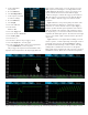
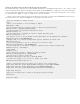
Figure 5
is a connection diagram for simultaneous input
current and output voltage measurement. The current
measurement is made via a standard pair of test leads connected
in series with the input high side of the power supply.
TSP Program
Cross-over cable for TSP-Link®
DC Load
Figure 5. Connection for simultaneous input current and output voltage
measurement
The Model DMM7510 has a dynamic current measurement
range from 0.1nA to 10A with a 100kHz analog bandwidth.
Compared to the current probe solution for oscilloscopes,
the ultra-low noise performance and the simplicity of current
connection using the Model DMM7510 often make it a better
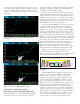
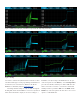
choice than current probing solutions. The screen captures in
Figure 6
are the results of a synchronized single trigger capture
of both input current and output voltage using a TSP script.
The synchronization achievable over the TSPLink
®
interface is
less than a few hundreds of nanoseconds. Once the individual
signals are acquired, you can overlay these two waveforms on a
single display. You can also split the waveforms into individual
lanes for a different viewing experience. The buck converter
clearly displays current-limiting behavior during the soft-start
sequence. Again, you can zoom and pan any area on these