
Datasheet


Characterizing Power-up and Power-down Transients
Using the Model DMM7510 7½-Digit Graphical
Sampling Multimeter
Introduction
Most electronic systems contain analog circuits, microprocessors,
DSPs, ASICs, and/or FPGAs, which require multiple supply
voltages. In order to ensure reliable and repeatable operation
of these systems, transient behaviors such as the power-up and
power-down timing, ramp rates, and the magnitude of different
supply voltages need to be appropriately controlled. Voltage and
current sizing, monitoring, sequencing, and tracking are essential
in characterizing the transient performance of power supplies.
Digital multimeter (DMM) is a very common instrument used
to evaluate many specifications of power supplies. However,
traditional DMMs often lack the ability to measure dynamic
events such as power-up and power-down transients. The
new Keithley Model DMM7510 7½-Digit Graphical Sampling
Multimeter has a secondary 18-bit sampling A-to-D converter
dedicated to digitizing rapidly changing voltage and current at
1Mega-sample per second. The digitizing functions employ the
same measurement ranges as the DMM’s traditional DC voltage
and current functions. In other words, the digitizer offers
exceptional dynamic range—from 1µV to 1000V and 100pA to
10A—which is suitable for many applications. The advanced
waveform triggering mechanisms such as edge, pulse, and
window triggering, allow you to easily capture, view, and interact
with these transient signals on the Model DMM7510’s multi-
touch display.
Background
Power-up and power-down transients are identified as step
functions in the input voltage that result from a relay or switch
closure. Achieving a clean or monotonic, rise or fall from various
power supplies can be a major concern. You may encounter
a sag in the input voltage due to a large inrush current and
finite power source impedance, which could cause catastrophic
problems with under-voltage lockout circuits, inrush current-
limiting circuits, and even generic power supplies. For example,
FPGAs contain auxiliary analog circuitry such as a phase-lock
loop (PLL) controlled by a voltage controlled oscillator (VCO).
The VCO would change frequencies and/or phase, causing the
PLL to lose synchronization when the supply voltage droops
during power-up. You may also encounter a slow ramp rate that
could lead to anomalous, sometimes destructive, consequences.
This application note illustrates how to capture, view, and
characterize power-up and power-down transients of a switch-
mode power supply (SMPS) on the front panel of the Keithley
Model DMM7510.
Switch-Mode Power Supply
A buck converter is a highly efficient switch mode DC-to-DC
voltage step-down converter. The following discussion is based
on Texas Instruments’ LM25088 DC-to-DC buck converter
evaluation board (EVM). It gives a steady 5V output from a 5.5V–
36V on the input. A proper power-up/power-down inspection can
ensure that the device turns on or off within a reasonable time
without any unexpected behaviors. These asynchronous transient
events can be captured using the analog waveform triggering
capability on the Model DMM7510.
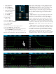
Making Connections from the Buck
Converter to the Model DMM7510
The buck converter can be connected to the Model DMM7510
using a standard pair of test leads, as shown in
Figure 1
. Properly
shielded test wires are recommended when measuring low-level
signals. To conduct the test, the buck converter is powered
by a programmable DC power supply. The output of the buck
converter is connected to an 8Ω resistive load.
DC Load
Figure 1. Power-up/power-down test connections.
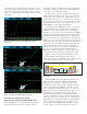
Setting Up the Power-up Test
from the Front Panel
The power-up transient can be easily captured by the Model
DMM7510. With only a handful of keystrokes to establish the
acquisition criteria, you can quickly view the waveform on the
DMM’s graphical display. We will utilize the built-in analog edge
triggering mechanism on the Graph user interface to set up the
sampling rate, trigger span, trigger slope, trigger level, as well
trigger position.
1. Press the POWER button on the front panel to turn on the
instrument.
2. On the FUNCTIONS swipe screen, select Digi V to select the
Digitize Voltage function.
3. Swipe to display the SETTINGS swipe screen.