
Datasheet


DIGITAL MULTIMETERS & SYSTEMS
www.keithley.com
1.888.KEITHLEY
(U.S. only)
A Greater Measure of Confidence
A Tektronix Company
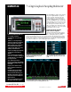
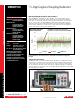
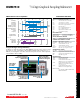
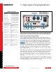
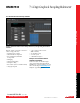
DMM7510
7½-Digit Graphical Sampling Multimeter
Specification Conditions
This document contains specifications and supplemental infor-
mation for the Model DMM7510 7½-Digit Graphical Sampling
Multimeter instrument. Specifications are the standards against
which the Model DMM7510 is tested. Upon leaving the factory,
the Model DMM7510 meets these specifications. Supplemental
and typical values are nonwarranted, apply at 23°C (73°F), and
are provided solely as useful information. Measurement accura-
cies are specified at the Model DMM7510 terminals under these
conditions:
• Temperature 23° ±5°C, 5% to 80% relative humidity, non-
condensing.
• After a 90-minute warmup period.
• 1 PLC or 5 PLC; for NPLC settings less than 1 PLC, add appro-
priate ppm of range for peak noise uncertainty from the RMS
noise table.
• Autozero enabled unless otherwise noted.
• Remote sense operation or properly zeroed local operation.
• Calibration period: One year or two years (calibration period
may vary depending on customer requirements).
• T
ACAL
= Ambient temperature of last automatic calibration.
• T
CAL
= Ambient temperature of last external calibration;
factory calibration performed at 23° ±1°C.
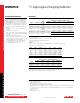
DC Voltage
ACCURACY (INPUT IMPEDANCE AUTO)
Range
1
Resolution
Input
Impedance
2
Accuracy ±(ppm of reading + ppm of range)
24 Hour
T
CAL
±1°C
2
90 Day
T
CAL
±5°C
1 Year
T
CAL
±5°C
2 Year
T
CAL
±5°C
Temperature
Coefficient
3
100.00000 mV
4
10 nV
>10 GΩ or
10 MΩ ±1 %
6 + 9 12 + 9 18 + 9 29 + 9 0.1 + 2.5
1.0000000 V
4
100 nV
>10 GΩ or
10 MΩ ±1 %
4 + 1 9 + 2 15+ 2 26 + 2 0.1 + 0.5
10.000000 V
4
1 µV
>10 GΩ or
10 MΩ ±1 %
2 + 0.7 9 + 1.2 14 + 1.2 22 + 1.2 0.1 + 0.05
100.00000 V
4
10 µV 10 MΩ ±1 % 8 + 3
(18 + 5)
5
(22 + 5)
5
(30 + 5)
5
(0.15 + 0.05)
5
35 + 5 40 + 5 45 + 5 2.0 + 0.5
1000.0000 V
4, 6
100 µV 10 MΩ ±1 % 8 + 3
(19 + 5)
5
(23 + 5)
5
(31 + 5)
5
(0.15 + 0.05)
5
35 + 5 40 + 5 45 + 4 2.0 + 0.5
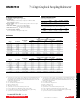
RMS NOISE (additional peak noise uncertainty)
7
• Applies to ±ppm of range.
• Peak noise uncertainty is included in DC specifications for ≥1 PLC.
• Add peak noise uncertainty to measurements for <1 PLC.
• Input impedance set to Auto.
Examples:
• 10V at 0.006 PLC: 1.2 (from Accuracy table) + 11 (additional peak noise uncertainty) = 12.2 ppm of range.
• 10V at 1 PLC: 1.2 + 0 = 1.2 ppm of range.
NPLC Digits 100 mV 1 V 10 V 100 V 1000 V
5 7½ 0.5 0.08 0.06 0.3 0.06
1 7½ 0.5 0.09 0.07 0.4 0.07
0.2
8
6½ 2 (10) 0.2 (1.6) 0.1 (1.1) 1.1 (9.4) 0.1 (1)
0.2 6½ 2 (12) 0.2 (1.6) 0.1 (1) 1.1 (8.9) 0.2 (1.1)
0.06 5½ 3 (17) 0.4 (2.7) 0.3 (2.1) 3 (17) 0.3 (2.4)
0.006 4½ 6 (42) 3 (18) 1 (11) 20 (100) 3 (18)
0.0005 3½ 30 (220) 20 (150) 20 (130) 120 (690) 20 (150)
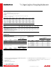
DC VOLTAGE SENSE ACCURACY
Accuracy ±(ppm of reading + ppm of range)
Range
24 Hour
T
CAL
±1°C
90 Day
T
CAL
±5°C
1 Year
T
CAL
±5°C
2 Year
T
CAL
±5°C
Temperature
Coefficient
9
100.00000 mV 6 + 14 12 + 14 18 + 14 29 + 14 0.1 + 2.5
1.0000000 V 4 + 1.5 9 + 3 15 + 3 26 + 3 0.1 + 0.5
10.00000 V 2 + 1.0 9 + 1.8 14 + 1.8 22 + 1.8 0.1 + 0.05
DC VOLTAGE RATIO
For input signals ≥1% of the range, ratio accuracy = ±[[V
INPUT
ppm of reading + V
INPUT
ppm of range * (V
INPUT
range/V
INPUT
input)] +
[V
SENSE
ppm of reading + V
SENSE
ppm of range * (V
SENSE
range/V
SENSE
input)]].
1. 20% overrange on all ranges except 1% for 1000V range.
2. Relative to calibration accuracy.
3. Add per degree from T
CAL
±5°C.
4. When properly zeroed using the Rel function with external cables.
5. Specified within 30 days of autocalibration, T
OPER
±5°C from T
ACAL
.
6. For signal levels greater than 500V, add 0.02 ppm/V to the ppm of the readings specification for measurements exceeding 500V.
7. Noise values are based on 1000 readings with autozero on and using low thermal 4-wire short. V
RMS
noise is typical. Additional
peak noise is guaranteed.
8. With line sync on.
9. Add per degree from T
CAL
±5°C.
Model DMM7510 condensed specifications
Model DMM7510 condensed specifications