
Datasheet
levels often ranging from tens of microamps to as low as tens
of nanoamps.
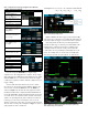
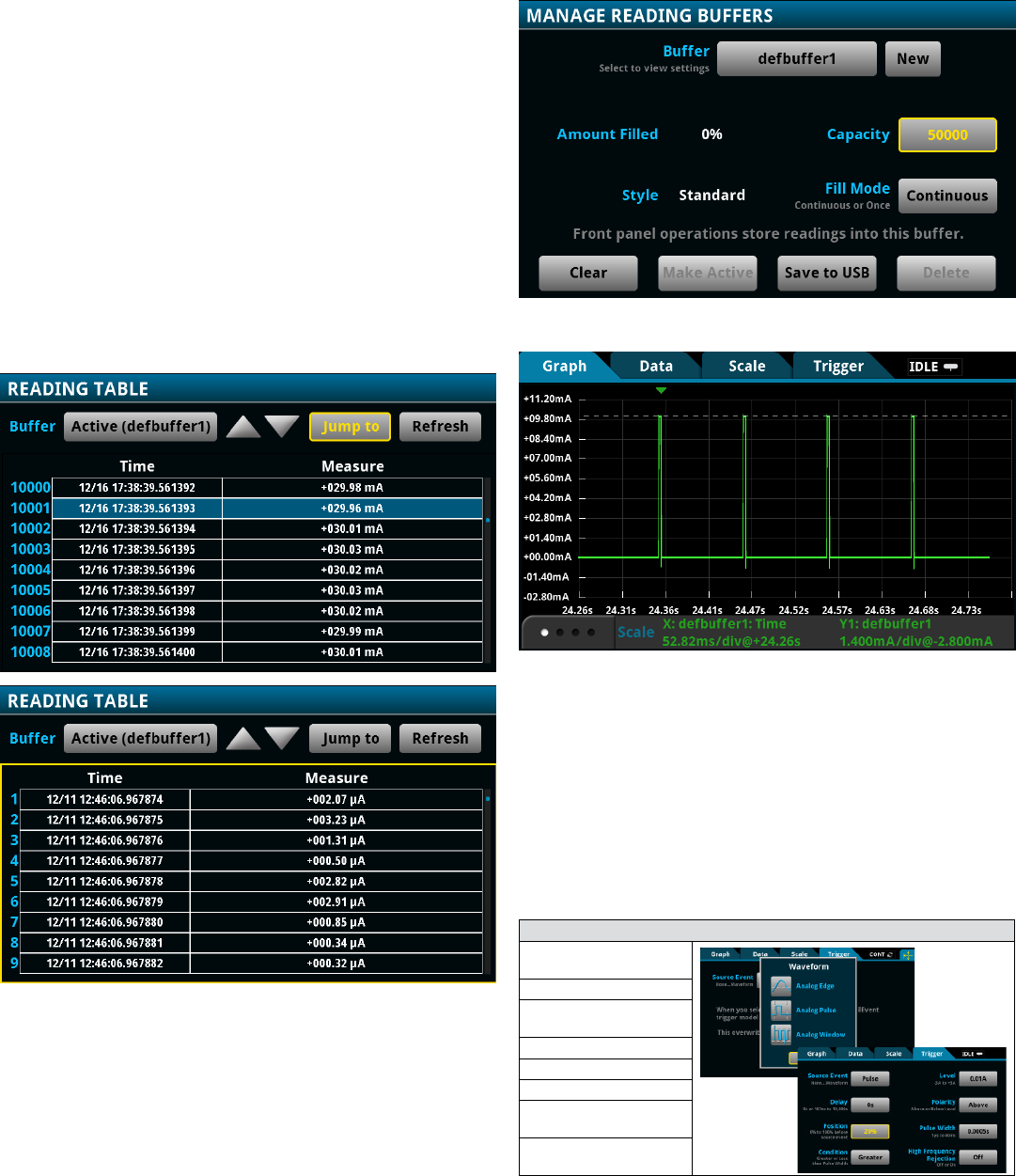
Figure 3
is an example of a multi-level idle mode current
pulse waveform captured on the 100µA range. The Model
DMM7510 is capable of resolving current below a few microamps.
All readings and timestamps are easily accessible through
the Reading Table under the main MENU. See
Figure 4
. To save
these readings to a thumbdrive, insert a USB thumbdrive in
the USB port on the front panel. Press the MENU key. Select
Reading Buffers, press the desired buffer, and then press Save
to USB. The data will be saved in the .csv format so it can later
be downloaded and imported into a spreadsheet. TIP: Press the
HOME and the ENTER keys on the front panel at the same time
to save a screen capture to a USB thumb drive.
Figure 4. Reading tables for the current pulse waveforms in Figures 1 (top)
and 3 (bottom).
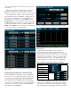
Observe Power Profile over a Period of Time
The Model DMM7510 is equipped with a large reading buffer
that can store up to 27.5 million time-stamped readings. This
is equivalent to 27.5 seconds of data acquired at 1Mega-sample
per second. The large buffer allows you to view the sensor
node operation over an extended period of time with multiple
occurrences of active and idle events. You can simply change the
acquisition span or the buffer capacity in the Reading Buffers
under MENU, as shown in
Figure 5
.
Figure 6
displays an example of active transmission,
represented by four 3ms, 10mA peak current pulses each
separated by a 100ms idle period. In addition to the analog edge
trigger mechanism discussed previously, you can use the built-in
analog pulse trigger mechanism to initiate an acquisition when
a specific profile of current pulse occurs.
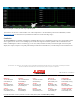
Table 2
lists the pulse
trigger configuration for the waveform captured in
Figure 6
.
Table 2. Configurations for Pulse Triggered Digitize Current Waveform
Configure trigger mechanism
Press the MENU key and
select Graph.
Select the Trigger tab.
Set Source Event
to Waveform.
Select Analog Pulse.
Set Level to 10mA.
Set Pulse Width to 500µs.
Set Condition to Greater
than 500µs.
Set Position to 20% for the
pre-trigger position.
You are able to zoom into a current pulse to show small
changes associated with different sensor node activities with a
reasonable level of resolution as shown in
Figure 7
. For example,
on the 100mA range, the 18-bit digitizer will produce readings at
Figure 5. Current pulse capture using the analog pulse trigger mechanism.
Figure 6. Increasing acquisition span for extended period of
waveform capture.