
Brochure


Section
7: Sampling temperature at a set time interval Model DMM7510 7½ Digit Multimeter
User's Manual
7-2 DMM7510-900-01 Rev. B / May 2015
Device connections
Use of a four-wire resistance temperature detector (RTD) reduces the effects of lead resistance on
accuracy and provides high stability.
You can use either the front or rear input terminals for this test. Both front-panel and rear-panel
connections are safety banana jacks. Note that you must use either the front terminals or the rear
terminals — you cannot mix front and rear connections.
Make sure that the front-panel TERMINALS switch is set to the terminals you are using. F displayed
next to the switch indicates that the instrument is reading the front-panel terminals. R indicates that
the instrument is reading the rear-panel terminals.
Make the following connections:
• Connect the red test leads to the SENSE HI and INPUT HI terminals.
• Connect the black test leads to the SENSE LO and INPUT LO terminals.
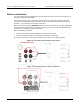
The physical connections for the front and rear panels are shown in the following figures.
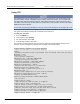
Figure 28: 4-wire RTD probe front-panel connections
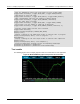
Figure 29: 4-wire RTD probe rear-panel connections