
Instructions


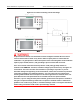
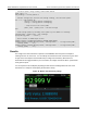
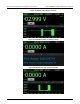
Table Of Contents
- Model DMM6500 6½-Digit Multimeter User's Manual
- 1 Introduction
- 2 Front-panel overview
- 3 Using a remote interface
- 4 Making basic front-panel measurements
- 5 Measuring DC voltage with high accuracy
- 6 Measuring 4-wire resistance with offset compensation
- 7 Scanning temperature at a set time interval
- 8 Grading and binning resistors
- 9 Measuring power using digitizing and TSP-Link
- 10 Troubleshooting FAQs
- About this section
- Where can I find updated drivers?
- Is there any software to help me get started?
- Why did my settings change?
- Why can't the DMM6500 read my USB flash drive?
- How do I upgrade the firmware?
- How do I change the command set?
- How do I save the present state of the instrument?
- How do I save what is displayed on the screen?
- What is the ethernet port number?
- 11 Next steps
- Contact information

Model DMM6500
6½ Digit Multimeter User's Manual Section 9: Measuring power using digitizing and TSP-
Link
DMM6500-900-01 Rev. B / August 2019 9-7
-- Calculate power using reading index-based method.
power_total = 0
num_readings = current_buffer.n
-- Iterate through each current and voltage reading, and calculate power.
for i = 1, num_readings do
current = current_buffer.readings[i]
voltage = voltage_buffer.readings[i]
-- Keep track of the total power
power_total = power_total + current*voltage
end
-- Find average power by dividing total power by the number of readings.
average_power = power_total / num_readings
print(average_power .. " Watts")
-- Print results to USER swipe screen.
node[1].display.changescreen(display.SCREEN_USER_SWIPE)
node[1].display.settext(display.TEXT2, "Average Power: ".. string.format("%8f",
average_power) .. " W")
node[2].display.settext(display.TEXT2, "Average Power: ".. string.format("%8f",
average_power) .. " W")
Results
The voltage and current waveforms captured on the DMM6500 show the power consumption
resulting from the use of the DUT. You can identify the transmission state of the device by the areas
of high current consumption and the visible drop in voltage from the battery. Because these
measurements are triggered within 2 µs of each other, the voltage and current data is synchronized
nearly point-for-point.
You can expand on this example by importing the data from the reading buffer from each of the
instruments to a computer and analyzing the data more closely.
Figure 45: Master node measuring voltage