
Instructions

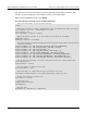
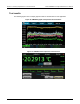
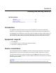

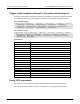
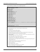
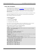

Table Of Contents
- Model DMM6500 6½-Digit Multimeter User's Manual
- 1 Introduction
- 2 Front-panel overview
- 3 Using a remote interface
- 4 Making basic front-panel measurements
- 5 Measuring DC voltage with high accuracy
- 6 Measuring 4-wire resistance with offset compensation
- 7 Scanning temperature at a set time interval
- 8 Grading and binning resistors
- 9 Measuring power using digitizing and TSP-Link
- 10 Troubleshooting FAQs
- About this section
- Where can I find updated drivers?
- Is there any software to help me get started?
- Why did my settings change?
- Why can't the DMM6500 read my USB flash drive?
- How do I upgrade the firmware?
- How do I change the command set?
- How do I save the present state of the instrument?
- How do I save what is displayed on the screen?
- What is the ethernet port number?
- 11 Next steps
- Contact information

Model DMM6500
6½ Digit Multimeter User's Manual Section 8:
Grading and binning resistors
DMM6500-900-01 Rev. B / August 2019 8-5
Send the following commands for this example application:
*RST
:TRAC:MAKE "bufferVar", 1000000
:TRAC:CLE "bufferVar"
:SENS:FUNC "FRES"
:SENS:FRES:NPLC 1
:SENS:AZER:ONCE
:SENS:FRES:OCOM ON
:DIGital:LINE1:MODE DIG, OUT
:DIG:LINE2:MODE DIG, OUT
:DIG:LINE3:MODE DIG, OUT
:DIG:LINE4:MODE DIG, OUT
:DIG:LINE1:STAT 0
:DIG:LINE2:STAT 0
:DIG:LINE3:STAT 0
:DIG:LINE4:STAT 0
:DIG:LINE5:MODE TRIG, IN
:TRIG:DIG5:IN:EDGE FALL
:DIG:LINE6:MODE TRIG, OUT
:TRIG:DIG6:OUT:LOG NEG
:TRIG:DIG6:OUT:PULS 10e-6
:TRIG:DIG6:OUT:STIM NOT1
:TRIG:LOAD "GradeBinning", 100, 5, .1, .1, 120, 80, 15, 4, 110, 90, 1, 105, 95, 2, 101,
99, 3, "bufferVar"
INIT
*WAI
:DISP:USER1: TEXT "Test Completed"
:DISP:SCR SWIPE_USER
Reset the DMM6500
Make a buffer named bufferVar with a capacity of 1,000,000 readings
Clear bufferVar
Set instrument to measure 4-wire resistance
Set the number of power line cycles (NPLC) to 1
Immediately update autozero reference measurements and then disable the autozero function
Enable offset compensation for more accurate resistance readings
Configure digital I/O lines 1 through 4 as digital outputs; these are used to output binning code to the
component handler
Set the states of digital I/O lines 1 through 4 to bit low
Configure digital I/O line 5 as trigger input to detect start-of-test trigger
Set trigger detector to detect falling edge on digital I/O line 5
Configure digital I/O line 6 as a trigger output used to send end-of-test trigger with negative logic and
output pulse width of 10 µs
The trigger pulse occurs when the Notify block generates an event
Define the GradeBinning trigger model template
Initiate the trigger model
Wait for the trigger model to complete
Display "Test Completed" when the binning test is complete
Set the front-panel display to the USER swipe screen