
Instructions

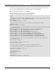

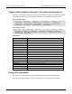
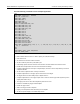
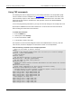

Table Of Contents
- Model DMM6500 6½-Digit Multimeter User's Manual
- 1 Introduction
- 2 Front-panel overview
- 3 Using a remote interface
- 4 Making basic front-panel measurements
- 5 Measuring DC voltage with high accuracy
- 6 Measuring 4-wire resistance with offset compensation
- 7 Scanning temperature at a set time interval
- 8 Grading and binning resistors
- 9 Measuring power using digitizing and TSP-Link
- 10 Troubleshooting FAQs
- About this section
- Where can I find updated drivers?
- Is there any software to help me get started?
- Why did my settings change?
- Why can't the DMM6500 read my USB flash drive?
- How do I upgrade the firmware?
- How do I change the command set?
- How do I save the present state of the instrument?
- How do I save what is displayed on the screen?
- What is the ethernet port number?
- 11 Next steps
- Contact information

Section
8: Grading and binning resistors Model DMM6500 6½ Digit Multimeter
User's Manual
8-4 DMM6500-900-01 Rev. B / August 2019
Trigger model template settings for the grade and binning test
The trigger model template contains the settings for the number of components, digital I/O, and limits.
The command parameters for the template are described in the following command and table.
SCPI command usage:
:TRIGger:LOAD "GradeBinning", <components>, <startInLine>, <startDelay>, <endDelay>,
<limit1High>, <limit1Low>, <limit1Pattern>, <allPattern>, <limit2High>,
<limit2Low>, <limit2Pattern>, <limit3High>, <limit3Low>, <limit3Pattern>,
<limit4High>, <limit4Low>, <limit4Pattern>, "<bufferName>"
TSP command usage:
trigger.model.load("GradeBinning", components, startInLine, startDelay, endDelay,
limit1High, limit1Low, limit1Pattern, allPattern, limit2High, limit2Low,
limit2Pattern, limit3High, limit3Low, limit3Pattern, limit4High, limit4Low,
limit4Pattern, bufferName)
Parameter list
components
100
startInLine
Digital I/O line 5
startDelay
100 ms
endDelay
100 ms
limit1High
R = 100 Ω, P = 20%, 100+20% = 120 Ω
limit1Low
R = 100 Ω, P = 20%, 100-20% = 80 Ω
limit1Pattern
Bin 1 Fail Pattern 15: Drive all digital I/O lines high (1111)
allPattern
All Pass Pattern 4: Drive line 3 high (0100)
limit2High
R = 100 Ω, P = 10%, 100+10% = 110 Ω
limit2Low
R = 100 Ω, P = 10%, 100-10% = 90 Ω
limit2Pattern
Bin 2 Fail Pattern 1: Drive line 1 high (0001)
limit3High
R = 100 Ω, P = 5%, 100+5% = 105 Ω
limit3Low
R = 100 Ω, P = 5%, 100
−
5% = 95 Ω
limit3Pattern
Bin 3 Fail Pattern 2: Drive line 2 high (0010)
limit4High
R = 100 Ω, P = 1%, 100+1% = 101 Ω
limit4Low
R = 100 Ω, P = 1%, 100
−
1% = 99 Ω
limit4Pattern
Bin 4 Fail Pattern 3: Drive line 1 and 2 high (0011)
bufferName
The reading buffer is set to bufferVar
Using SCPI commands
This sequence of SCPI commands grades resistors into bins based on measured accuracy.
You may need to make changes so that this code will run in your programming environment.