
Instructions

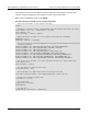

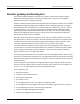
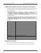
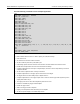
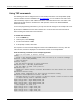

Table Of Contents
- Model DMM6500 6½-Digit Multimeter User's Manual
- 1 Introduction
- 2 Front-panel overview
- 3 Using a remote interface
- 4 Making basic front-panel measurements
- 5 Measuring DC voltage with high accuracy
- 6 Measuring 4-wire resistance with offset compensation
- 7 Scanning temperature at a set time interval
- 8 Grading and binning resistors
- 9 Measuring power using digitizing and TSP-Link
- 10 Troubleshooting FAQs
- About this section
- Where can I find updated drivers?
- Is there any software to help me get started?
- Why did my settings change?
- Why can't the DMM6500 read my USB flash drive?
- How do I upgrade the firmware?
- How do I change the command set?
- How do I save the present state of the instrument?
- How do I save what is displayed on the screen?
- What is the ethernet port number?
- 11 Next steps
- Contact information

Model DMM6500
6½ Digit Multimeter User's Manual Section 8:
Grading and binning resistors
DMM6500-900-01 Rev. B / August 2019 8-3
Resistor grading and binning test
This resistance-grading application uses limit tests to inspect a single resistor under test against
multiple limits until the first failure occurs. When the resistor fails, it is placed into a designated
resistance tolerance bin, as defined by the limits.
Resistors are placed into bins based on the bit patterns that are assigned to the limits. In this example,
the DMM6500 GradeBinning trigger model template is used to simplify the application. This trigger
model template grades components into four tolerance levels (for example, 20%, 10%, 5%, and 1%)
as defined by limits 1 to 4. A single spot measurement is inspected against multiple limits, which
tighten progressively around the same nominal value. Since there is no need to continue checking
limits once the appropriate tolerance level for a resistor under test is determined, this application
typically bins the tested resistors immediately.
Because the limits are inspected in ascending numeric order, the measured resistance is checked
first against Limit 1, which is the 20% limit. If the resistor fails this limit inspection, its resistance value
is outside of the 20% tolerance band, and the trigger model outputs the Limit 1 Fail Pattern, which
causes the component handler to place the resistor in the Limit 1 fail bin (20% fail bin).
If a resistor passes the 20% limit test, the resistance value is checked against Limit 2, which is the
10% limit value. If the resistor fails this limit inspection, the resistance is outside of the 10% tolerance
band. The trigger model outputs the Limit 2 Fail Pattern, which causes the component handler to
place the resistor in the Limit 2 fail bin (10% fail bin).
If a resistor passes the 10% limit test, the resistance value is checked against Limit 3, which is the 5%
limit value. If a resistor passes all the limit tests, the trigger model outputs the Overall Pass Bit Pattern,
which causes the component handler to place the resistor in the bin for components that have passed
all the limit checks.
For this example, the same fail pattern is assigned to both the lower and upper bounds of the limits.
Therefore, a fail bin contains resistance values in the range R−P% to R+P%. P in this example is 20,
10, 5, or 1. You can assign different bit patterns for different limit values.
For this application, you:
• Reset the instrument.
• Select the 4-wire resistance function.
• Enable offset compensation.
• Set autozero to once.
• Set up digital I/O lines one to four as outputs to component handler.
• Set up digital I/O line five for trigger-model control, detecting the trigger as the start-of-test input.
• Set up digital I/O line six as the end-of-test output notification.
• Initiate the GradeBinning trigger-model template.
• Display "Test Completed" on the front panel.