
Instructions

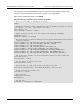

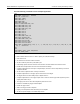
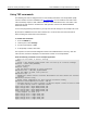

Table Of Contents
- Model DMM6500 6½-Digit Multimeter User's Manual
- 1 Introduction
- 2 Front-panel overview
- 3 Using a remote interface
- 4 Making basic front-panel measurements
- 5 Measuring DC voltage with high accuracy
- 6 Measuring 4-wire resistance with offset compensation
- 7 Scanning temperature at a set time interval
- 8 Grading and binning resistors
- 9 Measuring power using digitizing and TSP-Link
- 10 Troubleshooting FAQs
- About this section
- Where can I find updated drivers?
- Is there any software to help me get started?
- Why did my settings change?
- Why can't the DMM6500 read my USB flash drive?
- How do I upgrade the firmware?
- How do I change the command set?
- How do I save the present state of the instrument?
- How do I save what is displayed on the screen?
- What is the ethernet port number?
- 11 Next steps
- Contact information

In this section:
Introduction .............................................................................. 8-1
Equipment required .................................................................. 8-1
Device connections .................................................................. 8-1
Resistor grading and binning test ............................................. 8-3
Introduction
This application example demonstrates how to use the DMM6500 to perform benchtop binning
operations. It uses the trigger model and digital I/O to control external component-handling devices.
The DMM6500 can do simple pass-or-fail testing as well as grading and sorting. Grading resistors is a
common application that is done by monitoring multiple limits until the first failure. Binning resistors is
also common, but unlike grading, binning involves monitoring limits until the first pass is received.
Equipment required
• One DMM6500
• One computer set up for communication with the instrument
• One device or component to be tested
Device connections
This example application uses a DMM6500 to perform benchtop binning operations. Output signals
(grading results) are sent from the instrument to the component handler, which bins the devices.
The figure below shows the rear-panel connections from the DMM6500 to the test fixture and the
digital lines to the component handler. The optional GPIB communication card connects the controller
and the component handler.
Digital lines and GPIB communications require the KTTI-GPIB communications accessory card.
Section 8
Grading and binning resistors