
Instructions


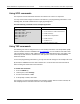
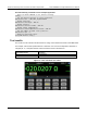

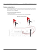

Table Of Contents
- Model DMM6500 6½-Digit Multimeter User's Manual
- 1 Introduction
- 2 Front-panel overview
- 3 Using a remote interface
- 4 Making basic front-panel measurements
- 5 Measuring DC voltage with high accuracy
- 6 Measuring 4-wire resistance with offset compensation
- 7 Scanning temperature at a set time interval
- 8 Grading and binning resistors
- 9 Measuring power using digitizing and TSP-Link
- 10 Troubleshooting FAQs
- About this section
- Where can I find updated drivers?
- Is there any software to help me get started?
- Why did my settings change?
- Why can't the DMM6500 read my USB flash drive?
- How do I upgrade the firmware?
- How do I change the command set?
- How do I save the present state of the instrument?
- How do I save what is displayed on the screen?
- What is the ethernet port number?
- 11 Next steps
- Contact information

Section
7: Scanning temperature at a set time interval Model DMM6500 6½ Digit Multimeter
User's Manual
7-4 DMM6500-900-01 Rev. B / August 2019
There is no internal connection between protective earth (safety ground) and the LO
terminals of the DMM6500. Therefore, hazardous voltages (more than 30 V
RMS
) can appear on
LO terminals. This can occur when the instrument is operating in any mode. To prevent
hazardous voltage from appearing on the LO terminals, connect the LO terminal to protective
earth (safety ground) if your application allows it. You can connect the LO terminal to the
chassis ground terminal on the front panel or the chassis ground screw terminal on the rear
panel. Note that the front-panel terminals are isolated from the rear-panel terminals.
Therefore, if you are using the front-panel terminals, ground to the front-panel LO terminal. If
you are using the rear-panel terminals, ground to the rear-panel LO terminal. Failure to follow
these guidelines can result in injury, death, or instrument damage.
Sample temperatures at a specific time interval
This example application uses the DMM6500 to scan a set of channels, measuring temperature at a
fixed interval. You can control the instrument from the front panel or over the remote interface using
SCPI code or TSP code. For information about setting up remote communications, see
Remote
communications interfaces (on page 3-1).
For this application, you will:
• Power on the instrument.
• Configure channels two through ten to measure temperature using type K thermocouples and the
internal reference junction.
• Use the Scan menu to set up a temperature scan of channels 2 to 10 that occurs every minute for
24 hours for a total of 1440 scans.
Using the front panel
To set up the application through the front panel:
1. Press the POWER button on the front panel to turn on the instrument.
2. Select the REAR terminals.
3. Swipe to the SCAN screen, then select Build Scan. The SCAN screen opens.
4. Select the + button.
5. Select channel 1, then select OK.
6. On the Measure Functions dialog box, select Temperature.
7. On the settings tab, set the Transducer to CJC 2001.
8. Select the + button.
9. Select channels 2 through 10 and select OK.
10. From the Function dialog box, select Temperature.