
Instructions
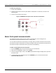

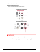

Table Of Contents
- Model DMM6500 6½-Digit Multimeter User's Manual
- 1 Introduction
- 2 Front-panel overview
- 3 Using a remote interface
- 4 Making basic front-panel measurements
- 5 Measuring DC voltage with high accuracy
- 6 Measuring 4-wire resistance with offset compensation
- 7 Scanning temperature at a set time interval
- 8 Grading and binning resistors
- 9 Measuring power using digitizing and TSP-Link
- 10 Troubleshooting FAQs
- About this section
- Where can I find updated drivers?
- Is there any software to help me get started?
- Why did my settings change?
- Why can't the DMM6500 read my USB flash drive?
- How do I upgrade the firmware?
- How do I change the command set?
- How do I save the present state of the instrument?
- How do I save what is displayed on the screen?
- What is the ethernet port number?
- 11 Next steps
- Contact information

In this section:
Introduction .............................................................................. 6-1
Equipment required .................................................................. 6-2
Device connections .................................................................. 6-2
Measuring 4-wire resistance with offset compensation ............ 6-4
Introduction
This application example demonstrates how to use the DMM6500 to accurately measure resistance.
Typically, when resistance measurements are made using the 2-wire method, the instrument sources
current through the test leads and the device under test (DUT). The voltage is measured and the
resistance is calculated.
It is difficult to obtain accurate 2-wire resistance measurements when the DUT has a resistance value
of less than 100 Ω. Typical lead resistances are from 1 mΩ to 10 mΩ. When the 2-wire method is
applied to low-resistance measurements, there is a small but significant voltage drop across the
resistance of each test lead. The voltage measured by the instrument is not the same as the voltage
directly across the DUT.
The 4-wire method is preferred for low-resistance measurements. With this configuration, the test
current is sourced through the DUT using one set of test leads, while a second set of SENSE leads
measures the voltage across the DUT. Connect the voltage-sensing leads as close to the DUT as
possible to avoid including the resistance of the test leads in the measurement.
Thermoelectric voltages (EMFs) can seriously affect low-resistance measurement accuracy. The
DMM6500 can apply the offset-compensated ohms method (OCOMP), which makes one normal
resistance measurement and one using the lowest current source setting to eliminate EMFs.
For this example, you use a 20 Ω resistor. Fixed measurement ranges are applied to optimize
scanning speed and OCOMP is applied to correct for any EMF effects.
For comprehensive information on 4-wire resistance measurements, thermoelectric EMFs, and offset
compensation methods, see the Low Level Measurements Handbook, available on tek.com/keithley
.
Section 6
Measuring 4-wire resistance with offset compensation