
Instructions


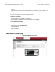

Table Of Contents
- Model DMM6500 6½-Digit Multimeter User's Manual
- 1 Introduction
- 2 Front-panel overview
- 3 Using a remote interface
- 4 Making basic front-panel measurements
- 5 Measuring DC voltage with high accuracy
- 6 Measuring 4-wire resistance with offset compensation
- 7 Scanning temperature at a set time interval
- 8 Grading and binning resistors
- 9 Measuring power using digitizing and TSP-Link
- 10 Troubleshooting FAQs
- About this section
- Where can I find updated drivers?
- Is there any software to help me get started?
- Why did my settings change?
- Why can't the DMM6500 read my USB flash drive?
- How do I upgrade the firmware?
- How do I change the command set?
- How do I save the present state of the instrument?
- How do I save what is displayed on the screen?
- What is the ethernet port number?
- 11 Next steps
- Contact information

Section
3: Using a remote interface Model DMM6500 6½ Digit Multimeter
User's Manual
3-16 DMM6500-900-01 Rev. B / August 2019
TSP-Link
You can communicate with the instrument using TSP-Link
®
if a KTTI-TSP communications accessory
card is installed in the instrument.
Keithley Instruments TSP-Link is a high-speed trigger synchronization and communication bus that
test-system builders can use to connect multiple instruments in a master and subordinate
configuration. Once connected, all the instruments that are equipped with TSP-Link in a system can
be programmed and operated under the control of the master instrument or instruments. This allows
the instruments to run tests more quickly because they can be decoupled from frequent computer
interaction. The test system can have multiple master and subordinate groups, which can be used to
handle multidevice testing in parallel. Combining TSP-Link with a flexible programmable trigger model
ensures speed.
Using TSP-Link, multiple instruments are connected and can be used as if they are part of the same
physical unit for simultaneous multichannel testing. The test system can be expanded to include up to
32 TSP-Link-enabled instruments.
The card provides six independently configurable digital input/output lines that can be used to control
external digital circuitry, for example, a handler that is used to perform binning operations. The digital
I/O port is a standard female DB-9 connector. You can also use these lines for triggering. The
instrument can generate output trigger pulses and detect input trigger pulses.
Install the KTTI-TSP accessory card
Figure 27: KTTI-TSP panel view
Unpack and inspect
Make sure to handle the KTTI-TSP card carefully. Always grasp the card by the side edges.
Do not touch board surfaces, components, or areas adjacent to electrical contacts.
Contamination from foreign materials such as dirt, dust, and body oils can substantially
degrade card performance.