
Instructions


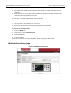

Table Of Contents
- Model DMM6500 6½-Digit Multimeter User's Manual
- 1 Introduction
- 2 Front-panel overview
- 3 Using a remote interface
- 4 Making basic front-panel measurements
- 5 Measuring DC voltage with high accuracy
- 6 Measuring 4-wire resistance with offset compensation
- 7 Scanning temperature at a set time interval
- 8 Grading and binning resistors
- 9 Measuring power using digitizing and TSP-Link
- 10 Troubleshooting FAQs
- About this section
- Where can I find updated drivers?
- Is there any software to help me get started?
- Why did my settings change?
- Why can't the DMM6500 read my USB flash drive?
- How do I upgrade the firmware?
- How do I change the command set?
- How do I save the present state of the instrument?
- How do I save what is displayed on the screen?
- What is the ethernet port number?
- 11 Next steps
- Contact information

Model DMM6500
6½ Digit Multimeter User's Manual Section 3:
Using a remote interface
DMM6500-900-01 Rev. B / August 2019 3-15
6. Reconnect the power line cable and any other cables to the rear panel.
7. Turn on the instrument.
Making connections
The RS-232 serial port can be connected to the serial port of a controller using a straight-through
RS232 cable terminated with DB-9 connectors. Do not use a null modem cable.
The serial port uses the transmit (TXD), receive (RXD), CTS and RTS (if flow control is enabled), and
signal ground (GND) lines of the RS232 standard. The figure below shows the rear-panel connector
for the RS232 interface. The table below shows the pinouts for the connector.
Figure 25: KTTI-RS232 panel view
Figure 26: RS-232 panel connector
Pin Description
1
No connection
2
TXD, transmit data
3
RXD, receive data
4
No connection
5
GND, signal ground
6
No connection
7
RTS, ready to send
8
CTS, clear to send
9
No connection
Additional information
Additional information is available in the KTTI-RS232 Communication and Digital I/O Accessory
Instruction Sheet, part number 0771436XX, where XX is the document revision number.