
Instructions


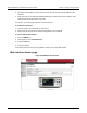

Table Of Contents
- Model DMM6500 6½-Digit Multimeter User's Manual
- 1 Introduction
- 2 Front-panel overview
- 3 Using a remote interface
- 4 Making basic front-panel measurements
- 5 Measuring DC voltage with high accuracy
- 6 Measuring 4-wire resistance with offset compensation
- 7 Scanning temperature at a set time interval
- 8 Grading and binning resistors
- 9 Measuring power using digitizing and TSP-Link
- 10 Troubleshooting FAQs
- About this section
- Where can I find updated drivers?
- Is there any software to help me get started?
- Why did my settings change?
- Why can't the DMM6500 read my USB flash drive?
- How do I upgrade the firmware?
- How do I change the command set?
- How do I save the present state of the instrument?
- How do I save what is displayed on the screen?
- What is the ethernet port number?
- 11 Next steps
- Contact information

Model DMM6500
6½ Digit Multimeter User's Manual Section 3: Usin
g a remote interface
DMM6500-900-01 Rev. B / August 2019 3-13
Set the GPIB address
The default GPIB address is 16. You can set the address from 1 to 30 if it is unique in the system.
This address cannot conflict with an address that is assigned to another instrument or to the GPIB
controller.
GPIB controllers are usually set to 0 or 21. To be safe, do not configure any instrument to have an
address of 21.
The instrument saves the address in nonvolatile memory. It does not change when you send a reset
command or when you turn the power off and on again.
To set the GPIB address from the front panel:
1. Press the MENU key.
2. Select Communication.
3. Select the GPIB tab.
4. Set the GPIB Address.
5. Select OK.
You can also set the GPIB address using remote commands. Set the GPIB address with the SCPI
command :SYSTem:GPIB:ADDRess or the TSP command gpib.address.
RS-232
You can communicate with the instrument using RS-232 if a KTTI-RS232 communications accessory
card is installed in the instrument.
The card provides six independently configurable digital input/output lines that can be used to control
external digital circuitry, for example, a handler that is used to perform binning operations. The digital
I/O port is a standard female DB-9 connector. You can also use these lines for triggering. The
instrument can generate output trigger pulses and detect input trigger pulses.